by Michael Rigby-Jones [mrjones@NORTELNETWORKS.COM]
                R
From 12v _____/\/\/\____________ To motor
           |__              |
              \>|           |
                |--/\/\/\---+
               /|    4k7
              |
              |

            To PIC (needs dropping to 5v for PIC)
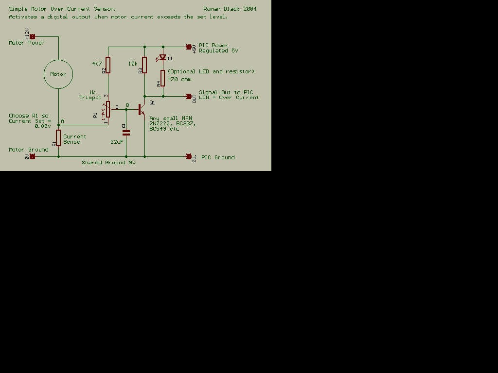
The transistor is a PNP device. Resistor R is chosen so that at the current you want to detect, the voltage drop across it is enough to switch on the transistor, say about 0.6 volts. The other resistor is to limit the current through the base/emitter junction.
So for 10 Amps this would give 0.6/10 =0.06 ohms. Not a very easilly obtainable value! But to achieve this kind of resistance you can experiment with a small coil of copper wire, you won't need much. Some commercial designs use a PCB track as the curent sense resistor.
Note that is circuit is not a precision design, the current at which it activates will vary a bit with temperature etc, but it should be OK just for detecting a stalling motor.
See also:

| file: /Techref/io/motor/overcurrent.htm, 1KB, , updated: 2006/11/3 11:03, local time: 2025/7/1 22:10,
216.73.216.82,10-3-5-33:LOG IN
|
| ©2025 These pages are served without commercial sponsorship. (No popup ads, etc...).Bandwidth abuse increases hosting cost forcing sponsorship or shutdown. This server aggressively defends against automated copying for any reason including offline viewing, duplication, etc... Please respect this requirement and DO NOT RIP THIS SITE. Questions? <A HREF="http://www.massmind.org/Techref/io/motor/overcurrent.htm"> Hardware Peripheral Input/Output </A> |
| Did you find what you needed? |
Welcome to massmind.org! |
|
Ashley Roll has put together a really nice little unit here. Leave off the MAX232 and keep these handy for the few times you need true RS232! |
.