A windmill takes energy from the wind (fluid) and produces power. The maximum theoretical power is 16/27 of the wind's power this is known as the "Betz limit". The wind’s energy, because it is moving, is in the form of kinetic energy and if all the energy was captured by the propeller or rotor there would not be an airflow consequently it can be said that the "lost" energy is used to keep the air flowing.
The maximum power available P is equal to –
K x D x A x V3
Where
It can be seen that by doubling the velocity of the wind the available power is increased eight times (2x2x2) and by doubling the blade diameter the available power is increased four times. When the power required is known and estimating the efficiency of the machine it is possible to size the rotor for the average wind speed available. Equally the efficiency that manufacturers claim can be calculated. It should be noted that when calculating the power available the efficiency of the total system should be used, that is, not only the generator and gearbox but also the transmission and storage.
Wind turbines have "rated outputs" which give the best output at a particular wind speed. But this output must not be taken to mean power available i.e. rated output x hours, as the wind speed is not constant and will vary from around 1/10 to 1/3 of the figure.
Efficiencies achieved in practice are much less than the theoretical 59.3%(16/27), that of a traditional windmill with a small number of sail-like blades is a little over 5%. However since wind is often available in practically unlimited quantities, this "efficiency" can become of little significance.
See also:
Probably the biggest issue with wind power is that the wind does not blow consistantly or well at ground level. Wind must be captured at a height. Height involves cost and, more importantly, danger from both the tower and the blades. The lighter and lower the windmill can be, the better.
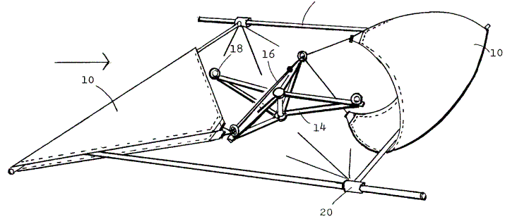
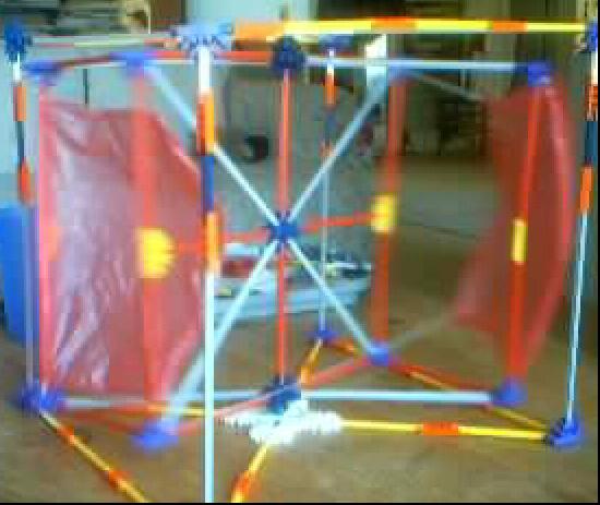
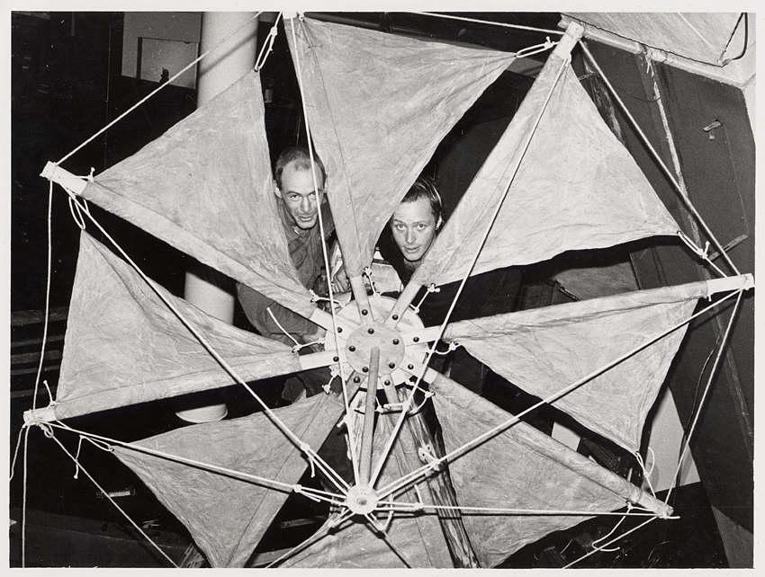
 FIGS.
1 and 2 are fragmentary views of the present invention that show the primary
elements in their relative size and arrangement. FIG. 1 is a fragmentary,
perspective view of the rotor with two of the four sails 10 in corresponding
phases. The invention resides in the provision of sails 10 that open and
close opposingly in conjunction with a frame structure 12, 14 that supports,
controls, shapes and rotates the sails 10 on a vertical shaft, and transmits
the energy to the ground through a shaft contained in a mast structure. The
sails 10 are fastened to the rim members 12 by two of its diagonal corners.
The two remaining diagonal corners are fastened to cables 16. The sails 10
communicate by the provision of the cables 16 and cable guides 18 to position
and limit the open and closed phases.
FIGS.
1 and 2 are fragmentary views of the present invention that show the primary
elements in their relative size and arrangement. FIG. 1 is a fragmentary,
perspective view of the rotor with two of the four sails 10 in corresponding
phases. The invention resides in the provision of sails 10 that open and
close opposingly in conjunction with a frame structure 12, 14 that supports,
controls, shapes and rotates the sails 10 on a vertical shaft, and transmits
the energy to the ground through a shaft contained in a mast structure. The
sails 10 are fastened to the rim members 12 by two of its diagonal corners.
The two remaining diagonal corners are fastened to cables 16. The sails 10
communicate by the provision of the cables 16 and cable guides 18 to position
and limit the open and closed phases.
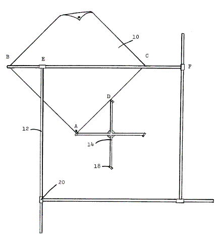
FIG. 2 is a top view of the invention in its preferred form showing the relative size of the basic components of the rotor. The operation is dependent on the proportion and arrangement of the rim 12, hub 14, guides 18, and sails 10. The proportion and arrangement of these components remain consistent while the size of the complete rotor assembly can vary according to desired power and local wind conditions. The proportions are as follows: The sails 10 form a square and determine the size of the other components. The hub 14 forms a square with a cable guide 18 at each corner. The measurement of a side of the hub 18 (AD) is one half of a side of the sail 10 (AB). The rim 12 forms a square where the rim elements connect 20. The measurement between these points (EF) is the same as the diagonal measurement of the sail 10 (BC). The extended portion of the rim members (BE) measures one quarter of the diagonal measurement of the sail 10 (BC).
Specifications of a typical rotor are as follows: Sails 10 made from Dacron fabric with the dimension 2 m..times.2 m. reside on a frame in which the hub 14 measures 1 m..times.1 m. The rim 12 measures 2.828 m. between the rim connectors 20. The extended portion of the rim measures 0.7 m. The total length of a rim member is 3.52 m. Typically, rim 12 and hub 14 components are made of galvanized tubular steel (with diameters of 2.3 cm. and 1.8 cm. respectively) of the type commonly used for electrical conduit.
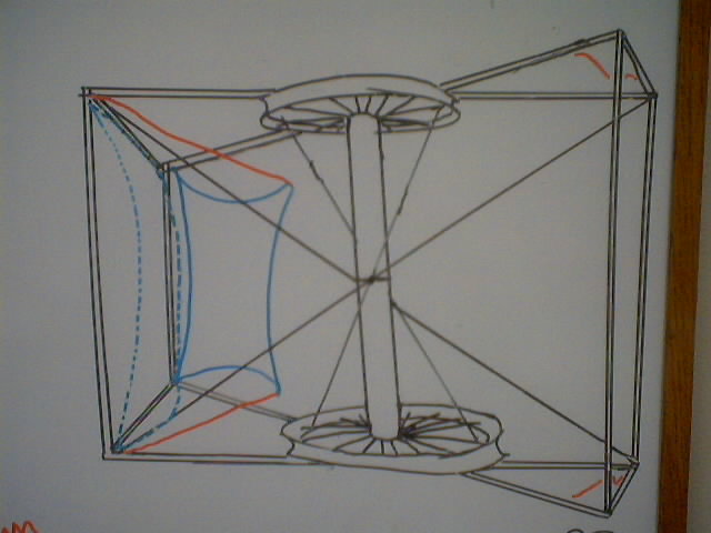
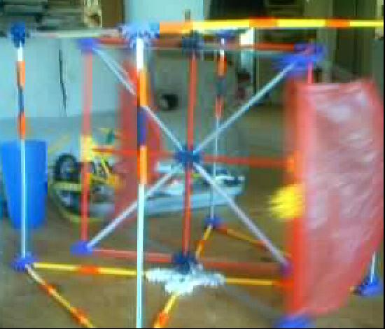
The two sails (one on each side) are tied closely at the outside trailing edge and attached via lines through pullys at the outside leading edge back past the center post to the matching line on the other sail. In the drawing at left, the right sail (not shown) pulls the left sail into a reach when it is in a run. The lines shown in red would be pulled tight on the left side so that the inner, free, edge of the left sail is pulled tight against the outer leading pole. In the prototype at right, in light wind, you can actually see the rotor accellerate as the reaching sail enters the wind, and this is despite the fact that the running sail has been in a run (using the sailing sense of the word) for some time.
None of this is terribly effecient or effective except for this: It will produce usefull work in very low winds due to the large area of the sail and will not be distroyed in high winds because the sails luft so much more as they tack. It is actually a very bad design for high winds and will not produce anywhere near the power that a standard windmill will produce from a good stiff wind. But it will produce a regular, usefull, output over a much larger range of wind speeds and will do useful work at very low speeds where a conventional windmill will not produce any result. It might produce useful work at ground level. It requires a support at the top as well as the bottom and that is a difficult thing to do.
As suggested by Bill Roberts, this can be tilted at 45' (the wind doesn't care if its straight) and the lower shaft extended down as a six inch or so plastic pipe with a 1" rubber or clear plastic tube wrapped around it to make an archemedies screw pump for raiseing water. Usefull for pond heating or filters.
This variation is released to the public domain and licenced under the GPL but since it is clearly based on a patented item, I would not suggest you try to sell it.
 The Rhizome
Collective built a windmill from a bicycle wheel: "This device is a windmill
built from bicycle parts. It differs from most windmills in that it faces
only one direction, but this is made up for by its simplicity. It works well
in an area with a strong prevailing wind from one direction. It is designed
to be able to catch even slight breezes. The weight of the pump rod is eliminated
by lightweight nylon strings. This windmill operates a water pump made from
an old bicycle pump. It serves to circulate the water in the pond (not a
critical function), but could be used to pump water several feet vertically.
In higher wind areas it could conceivably be used to generate electricity.
Total construction cost when using easily findable salvage materials is less
than $30. "
The Rhizome
Collective built a windmill from a bicycle wheel: "This device is a windmill
built from bicycle parts. It differs from most windmills in that it faces
only one direction, but this is made up for by its simplicity. It works well
in an area with a strong prevailing wind from one direction. It is designed
to be able to catch even slight breezes. The weight of the pump rod is eliminated
by lightweight nylon strings. This windmill operates a water pump made from
an old bicycle pump. It serves to circulate the water in the pond (not a
critical function), but could be used to pump water several feet vertically.
In higher wind areas it could conceivably be used to generate electricity.
Total construction cost when using easily findable salvage materials is less
than $30. "
See:
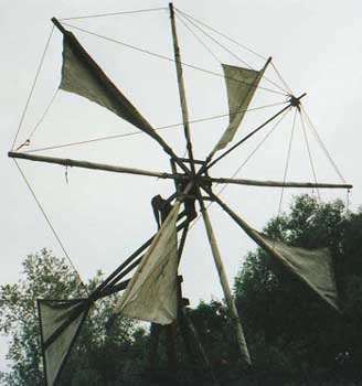 This rotor is of a type that is also used on Crete (An island
in the Mediterranean Sea), and has a diameter of 6 meter. The windmill has
no brake to stop it if storm is coming. The sails must be rolled in. With
a certain mechanism, which transfers a rotating movement in a vertical one,
the rotor drives a piston pump. This allows the windmill to pump up water
from a maximum of 15 meter. With a wind speed of 4 meter per second ( 3 Beaufort)
the mill delivers 15 litres per minute if the height difference is 10 meter.
If the height difference is less, the mill will deliver more. To build the
windmill tools for woodworking are necessary.
This rotor is of a type that is also used on Crete (An island
in the Mediterranean Sea), and has a diameter of 6 meter. The windmill has
no brake to stop it if storm is coming. The sails must be rolled in. With
a certain mechanism, which transfers a rotating movement in a vertical one,
the rotor drives a piston pump. This allows the windmill to pump up water
from a maximum of 15 meter. With a wind speed of 4 meter per second ( 3 Beaufort)
the mill delivers 15 litres per minute if the height difference is 10 meter.
If the height difference is less, the mill will deliver more. To build the
windmill tools for woodworking are necessary.
Here is another VAWT (Vertical Axis Wind Turbine) with blades that are activly turned to catch the wind. http://www.thebackshed.com/Windmill/photos2.asp
Olin Lathrop of embedinc.com generated an animation of his verison of this design (which he came up with independantly) that shows the basic principle:
The gear in the center would be attached to a wind vane and always points in the direction the wind is blowing. In this animation, that is away from us, into the picture. The blades on the right side are turned to catch the air and those on the left are always turned edge on to the wind.
http://www.windstuffnow.com/main/darrieus_type.htm
There are several variations of Savonius rotor that I have seen, all of which work well. The efficiency of a Savonius is only around 15 per cent but they are ideal for many situations. Some variations are shown below, looking down from the top of the turbine.
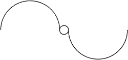 Good.
It is very strong due to the central shaft, but sligtly less efficient than
the other two. However, the extra strength allows the rotor to be supported
at one end only.
Good.
It is very strong due to the central shaft, but sligtly less efficient than
the other two. However, the extra strength allows the rotor to be supported
at one end only.
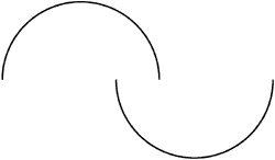 This
design is also very simple, and can also be made easily from metal drums
or pipe sections. The design is slightly more efficient than the one above
as some of the air is deflected by the second vane as it exits the first
one.
This
design is also very simple, and can also be made easily from metal drums
or pipe sections. The design is slightly more efficient than the one above
as some of the air is deflected by the second vane as it exits the first
one.
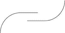 This
is the most efficient Savonius design. It not only has the advantage of air
being deflected twice like the design above, but also that the vanes act
partly like an airfoil when they are edge-on into the wind, creating a small
lift effect and thus enhancing efficiency. This design is much more difficult
to build, requiring vanes rolled from metal sheet instead of being cut from
drums or pipes.
This
is the most efficient Savonius design. It not only has the advantage of air
being deflected twice like the design above, but also that the vanes act
partly like an airfoil when they are edge-on into the wind, creating a small
lift effect and thus enhancing efficiency. This design is much more difficult
to build, requiring vanes rolled from metal sheet instead of being cut from
drums or pipes.
See also:
 Take one kit on a
string. Make the string a loop. Add kits all around the loop. Make the kits
at the top fold so they fall down the back of the loop and re-open at the
ground. +
Take one kit on a
string. Make the string a loop. Add kits all around the loop. Make the kits
at the top fold so they fall down the back of the loop and re-open at the
ground. +
Also:
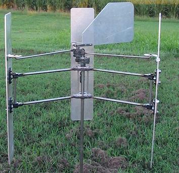
One of the more interesting tradeoffs in windmill design is between the area swept by the blades (or other surface) and the speed of the shaft. Conventional windmills use very large blades sweeping a huge area from a central hub. But as the blade gets longer, that hub turns slower. To generate electricity, or really any useful work, you need a shaft spinning quickly. So at the top of those huge windmills, there is a huge, and very strong, gearbox between the input shaft and the generator. That gearbox is very expesive, heavy, contains many moving parts, and requires regular maintenance to avoid failure.
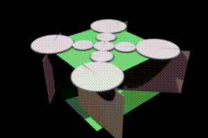
Instead of one very large blade, use many smaller blades on the same shaft, with a slight offset so each blade sees new wind. (text below quoted from FAQ at selsam.com)
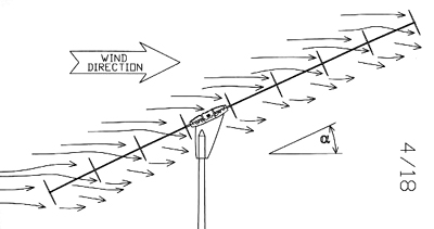 This does result in some loss as the deflected air from one rotor
may interfer with the next, but given sufficient spacing and angle, the loss
is acceptable. And the interferrence actually helps to regulate speed (see
below)
This does result in some loss as the deflected air from one rotor
may interfer with the next, but given sufficient spacing and angle, the loss
is acceptable. And the interferrence actually helps to regulate speed (see
below)
Having a slight deviation between the plane of each rotor and the wind direction has almost no effect on performance.
Note that no "tail" or other means of orienting the array is necessary if we place the center of aerodynamic drag of the entire driveshaft with its attached rotors slightly downwind of an azimuthal pivot point; the machine will faithfully stay headed windward.
Protection in high winds can be provided if a flexable shaft, such as carbon fiber, is used. Several factors act to protect the machine in high winds: First, at the higher reynolds numbers that come with increasing wind speeds, the length of wind shadows effectively increases, so that upwind rotors will begin to protect downwind rotors. More importantly, the downwind section of the shaft will tend to bend to a more horizontal direction, placing downwind rotors more into the wind shadows of the upwind ones. Finally, the generator and shaft can be resiliently mounted, so that they are blown into a more horizontal orientation by very strong winds, so that overall rotor exposure is reduced, while power output and rpm are maintained. They key to proper behavior at all wind speeds is that progressively more rotor surface is exposed in low winds, and less in high winds. No furling cycle is involved, so there is never a time when no power is generated because of excessively strong winds. The action is also not as radical as furling, and is less prone to "finicky" behavior.
Comments:
| file: /Techref/other/windmills.htm, 20KB, , updated: 2018/11/14 17:26, local time: 2025/9/18 17:03,
owner: JMN-EFP-786,
216.73.216.28,10-1-97-167:LOG IN
|
| ©2025 These pages are served without commercial sponsorship. (No popup ads, etc...).Bandwidth abuse increases hosting cost forcing sponsorship or shutdown. This server aggressively defends against automated copying for any reason including offline viewing, duplication, etc... Please respect this requirement and DO NOT RIP THIS SITE. Questions? <A HREF="http://www.massmind.org/Techref/other/windmills.htm"> Wind Energy</A> |
| Did you find what you needed? |
Welcome to massmind.org! |
Welcome to www.massmind.org! |
.