I want to explain a little bit about my Epson inkjet adventure; why and how it is started. While planning to buy a new computer, I visited local shop and decided on what to buy. They said that they have special deal on selected Epson models; up to $50 off from the retail price. Wow, not a bad idea but what about ink prices, will buying Epson ink suck my blood? Yes, definitely, but the solution is to refill. I said ok and bought a CX4200. I did some printouts on paper and transparency; its resolution seems very good but what about accuracy? On x-axis it is also very good but y-axis is not so accurate since it uses friction feed. On the other hand, if you print the same image on several sheets they seem to match each other very well.
My first problem was how to refill/reset Epson inkjet cartridges. I did some
web search and found that many people said the best one was,
http://www.eddiem.com/photo/printer/chipreset/resetchip.html
Instead of buying a ready solution I have decided use Eddie's reseter and port linux version of his program to Cygwin. {ed: source} It really works very well.
I bought also refill inks from MIS-Pro, refilled the cartridges with it and reset them with my reseter.
 Ink Cartridges 1024x768px 24b 98.79 KB |
To refill the cartridges, I opened a hole on top of cartridges and filled them with ink using syringe and then sealed the holes with hot glue. The result is perfect! No problem.
Now, I don't want to use printers for just paper/photo printing: I want to print PCB/panel or even do 3-D rapid prototyping in future. After doing some experiments on transparency, I realized that I can create a master for photo-resist/dryfilm. The resolution of the image is good enough to use it as a master but it is a hassle to do photo-resist printing; it just needs so many steps. What about direct printing?
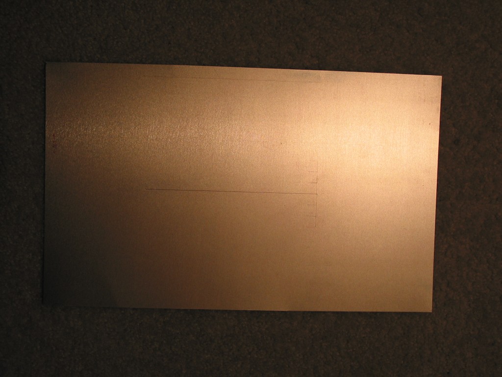
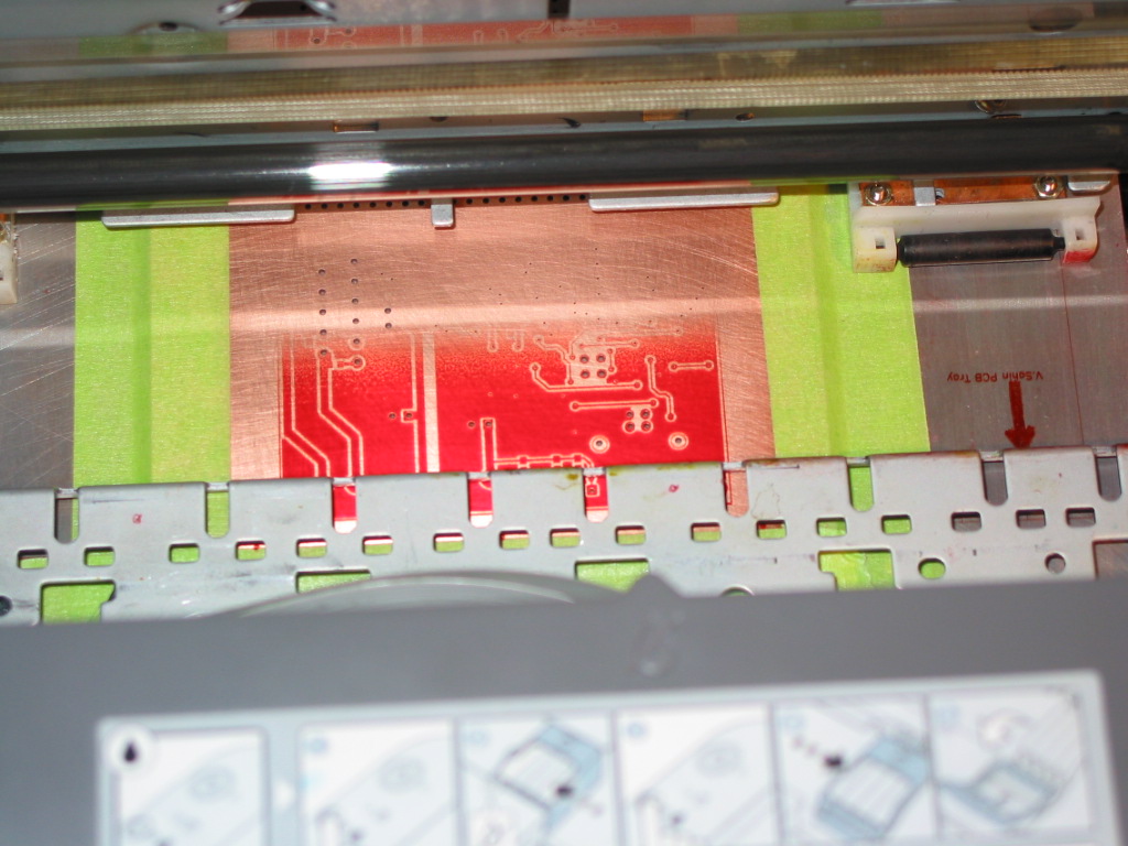
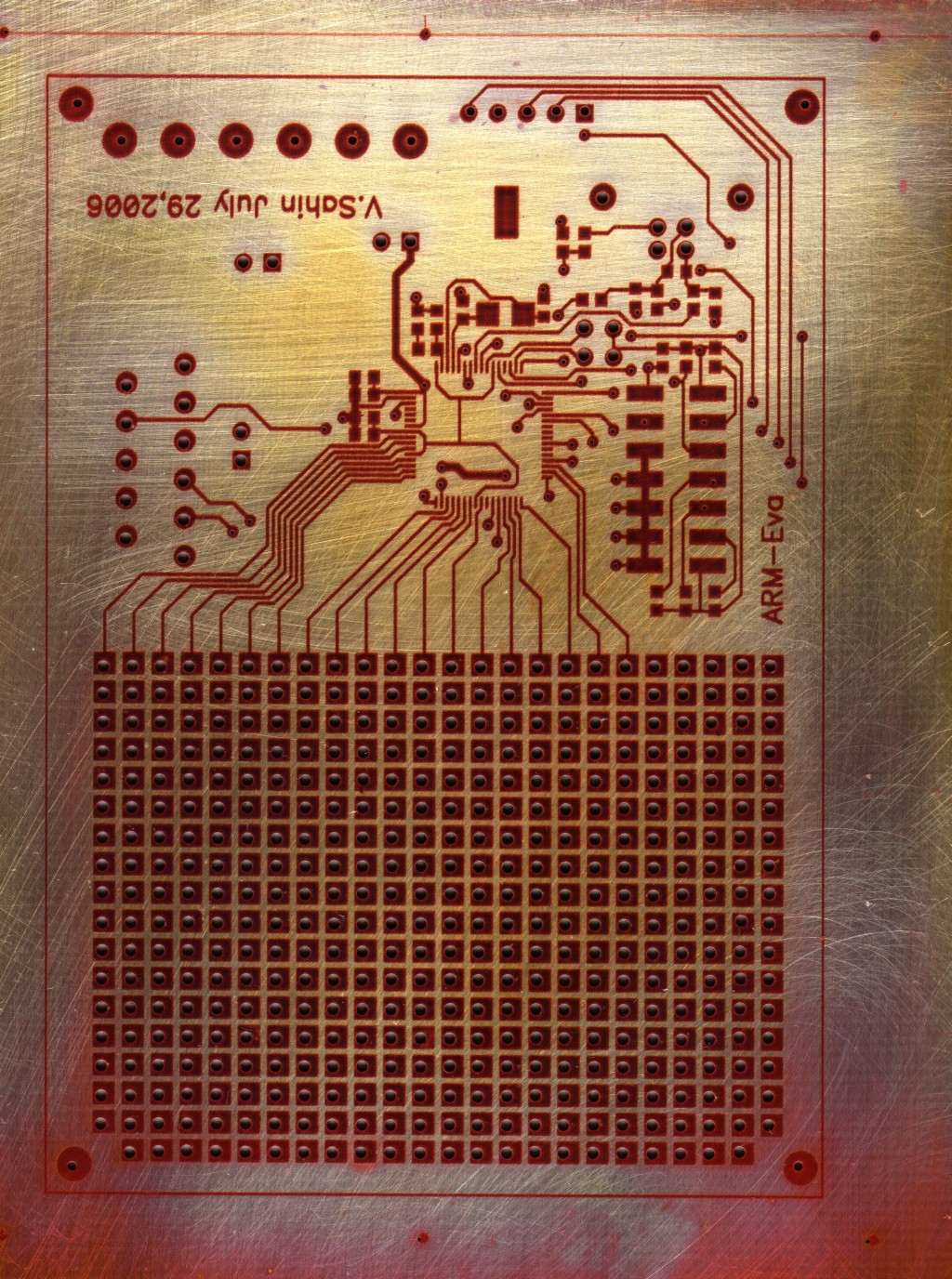
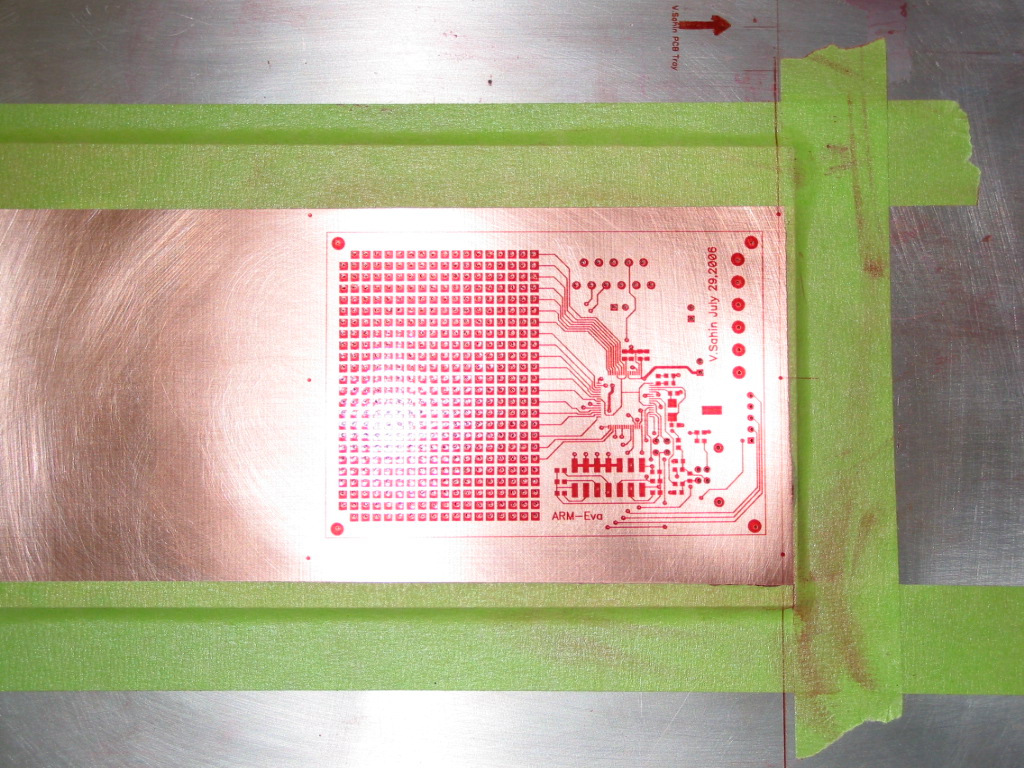
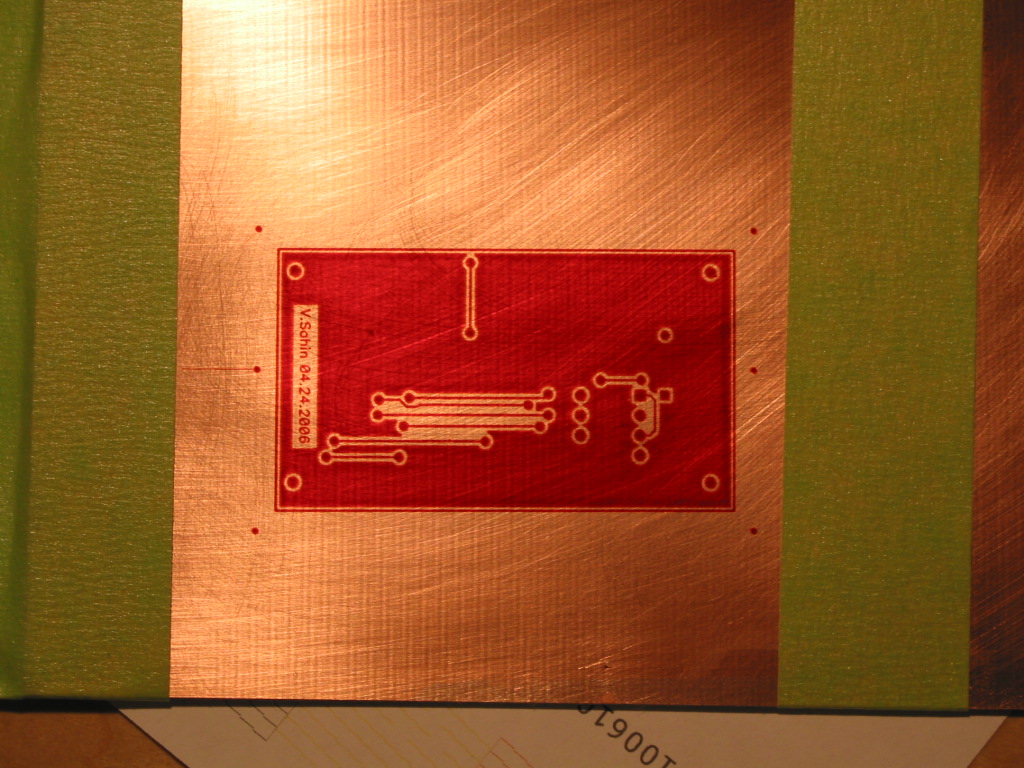
I decided to do some experiments with the paper thin (0.005” / 130 micrometer) PCB stock I got from eBay some time ago. I did a very good cleaning on a PCB and gave it a try. Another wow, perfect! Excellent quality:
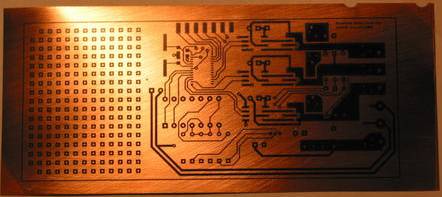
I cured the PCB by holding it about an inch above one of the burners on my stove until the ink was almost burned and decided to etch it:
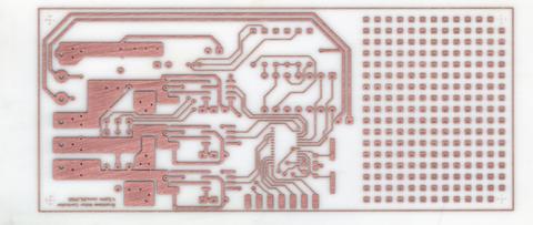
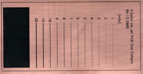
Surprise! The ink is also etch resistant. This is when I first shared the results in Yahoo Homebrew_PCBs^ group. I also did some performance tests to see the limits:
and etched version:
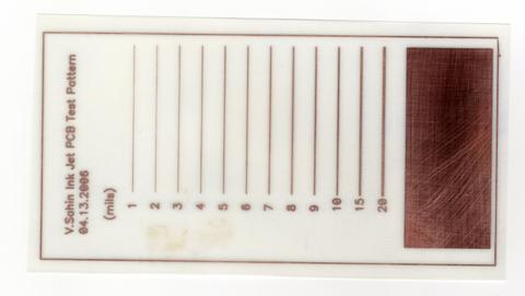
The traces have some breakage below 3 mil because of under etching or maybe printer resolution. I am satisfied with the initial results. Till now everything was so smooth I didn't realize it is an iceberg.
I have defined my goals at this point. I don't want to loose so much time on PCB prototyping, it should be automatic as much as possible and no more hand drilling. I want to be able to do double side printing on a CNC drilled PCB since 99% of my prototypes are double sided. So, it was time to modify the printer to accept standard 1/16” (1.6mm) PCB stock.
CAUTION
These modifications can result in damage to your printer. We have no responsibility in any case. We are only sharing our experiences; use it at your own risk. If you don't have enough experience in mechanics and electronics please don't try to modify your printer. Do not contact the author with questions except via the Yahoo forum^.
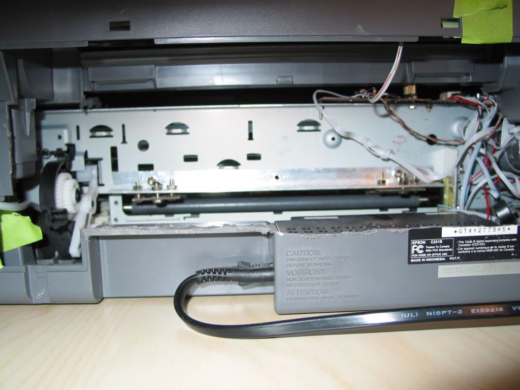
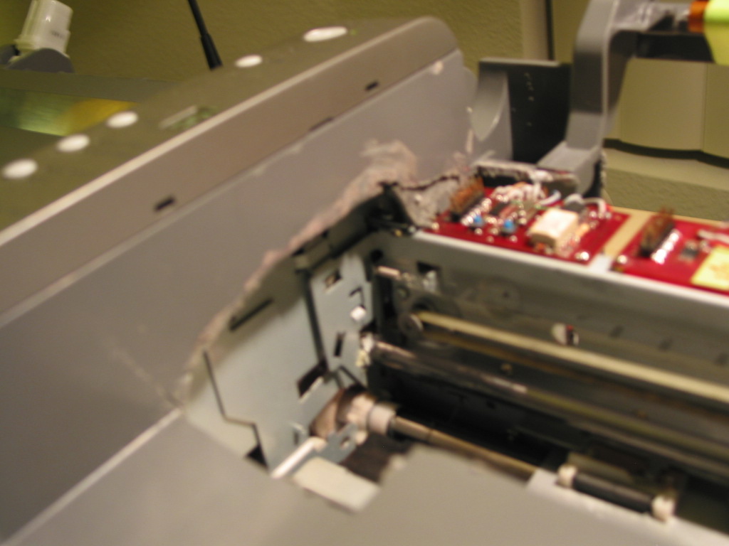
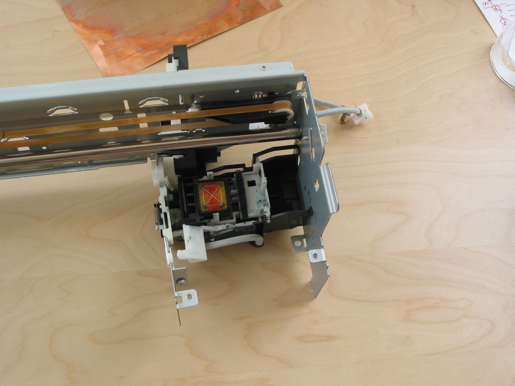
I started to disassemble printer:
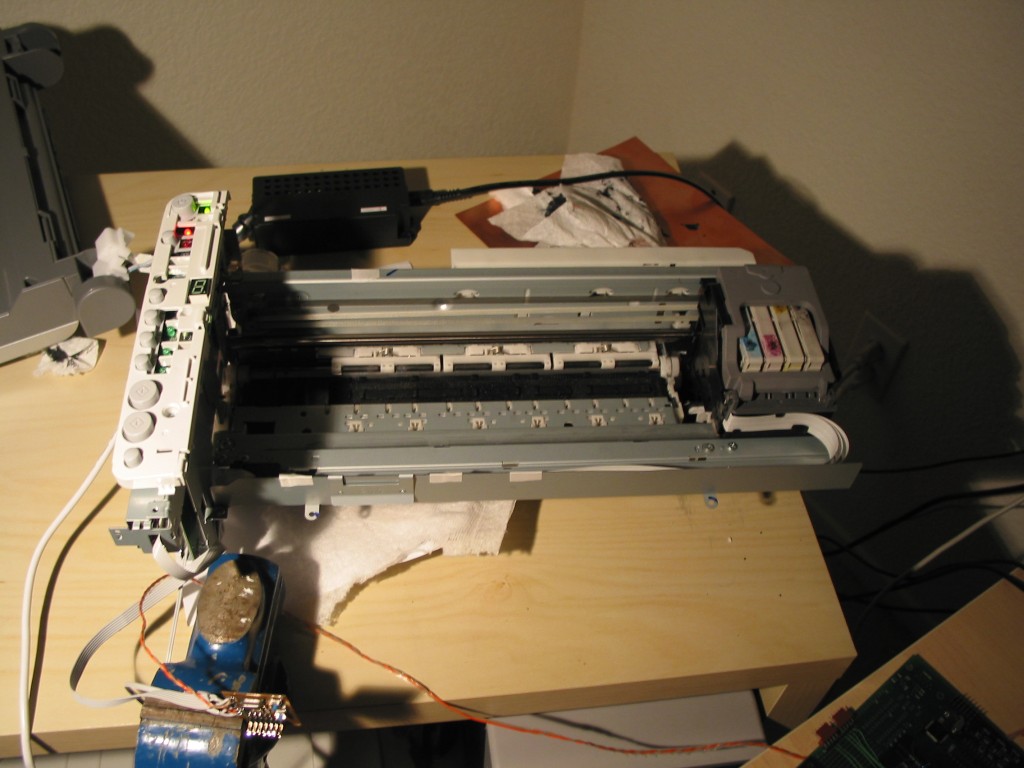
Unassembled
CX4200 with devboard
1024x768px
24b 137.26KB
and check the sensors. The printer uses DC servos for x/y axis positioning and it has a total of 2 optical encoders on the x and y axis. It has 1 slotted optical sensor for paper end detection mounted on the rear and 1 paper sensor mounted on the ink jet head; this sensor is used to sense objects on the printing area and to find the edge of the paper. During initial scanning, the printing area is checked to make sure that there is no object around. This sensor is completely analog and uses the reflection from the black plastic in the printing area. So if you remove it you will have trouble. Instead, I built a microcontroller board to sample x/y encoders, paper sensor and paper end sensor and recorded the behavior of the printer.
After getting all the data I modified the software in the microcontroller to emulate the paper.
//*******************************************************************************
//  MSP-FET430F123 Epson CX4200 Paper Emulator
//  Written by: Volkan Sahin
//  First Edit: May 29, 2006
//  Version: Beta
//  This software is under the GNU Public License (GPL)
//  I am not responsible for any damage that happens to your printer by using this software.
//  Use at your own risk.
//  Built with MSPGCC
//  Pressing SW2 for a long time (~ 3 secs) activates relay and Led201 starts to blink.
//  I added  this for future use, such as to turn off the Y-axis motor.
//  Pressing SW2 for a short period (~1 sec) and then releasing activates paper emulator.
//  XENC0/XENC1 quadrature inputs of X-axis encoder (on inkjet head)
//  YENC0/YENC1 quadrature inputs of Y-axis encoder (on mainboard)
//  TRAYHOME tray slot detector input
//  PDETECT Paper sensor (on inkjet head) connection.
//  PSWITCH Paper end sensor connection
//  Connect PDETECT/PSWITCH signals in parallel to sensors on printer.
//  You can find unused variables, sorry for that, feel free to remove them.
//******************************************************************************
#include <io.h>
#include <signal.h>
#include <stdio.h>
#include  <msp430x12x.h>
#include <string.h>
#define SYSTEMCLK  8000000
#define BAUDRATE   38400

#define TICKRATE 10000
#define CLKOUT 1000000   //Ref. Osc of MSP 8MHz & TIMER Prescaler set to 8
#define CAPTURECONSTANT 37500 //300ms


#define TICKCONSTANT 10
#define UARTRXTIMEOUT 100

#define  MASK_10  0x369
#define  MASK_10B 0x96


//Port 1 Connections

#define dummy  0x10    // P1.4   IO Mode = Output
#define SWIN  0x08  // P1.3   IO Mode =  INPUT
#define MSM 0x04 // P1.2   IO Mode = Input
#define MSP 0x02  // P1.1  IO Mode = Input

//Port 2 Connections
#define NC1    0x80  // P2.7   IO Mode = Output
#define NC0    0x40  // P2.6   IO Mode = Output
#define XENC1  0x20 // P2.5   IO Mode = INPUT
#define YENC1  0x10  // P2.4   IO Mode =  INPUT
#define XENC0  0x08  // P2.3   IO Mode =  INPUT
#define YENC0  0x04 // P2.2   IO Mode =  INPUT
#define PSWITCH 0x02  // P2.1   IO Mode =  INPUT
#define PDETECT 0x01   // P2.0   IO Mode =  INPUT

//Port 3 Connections
#define TRAYHOME  0x10  // P3.4   IO Mode = Input
#define RLY 0x20 // P3.5 IO Mode = Output
#define LED201 0x08  // P3.3   IO Mode = Output


//#define genclk   P1OUT ^= SCK; _NOP(); _NOP();_NOP(); _NOP(); P1OUT ^= SCK; _NOP(); _NOP();_NOP(); _NOP()

#define EVENT_PATTERN 0x01
#define EVENT_TIMER_EXPIRED 0x02
#define EVENT_SIZE_INFO 0x04
#define EVENT_TX_EMPTY  0x08
#define EVENT_UART_TX_EMPTY 0x10
#define EVENT_UART_RX_FULL 0x20
#define EVENT_UART_RX_TIMEOUT 0x40
#define EVENT_NEXT_WORD 0x80
//#define PPOS  0x9f0+0x4f8 //old setting
//#define PPOS  0xe0e
#define PPOS  0xd90
#define PPOSLOWER  0xd26
//PPOS range=0xd26 to 0xef7;mid point= 0xe0e

static volatile unsigned int timetick;
static volatile unsigned int bitcounter;
static volatile unsigned char Event_Status;
static volatile unsigned char i,wdtcnt=32;

static volatile unsigned char start = 0;
static volatile unsigned char clk,addr=0,data,bit_data=0;
static volatile unsigned char  state=0;
static volatile unsigned int totalclk=0;
//static volatile unsigned char *ptr,timercnt = 10;
static volatile unsigned char *ptr;
//volatile unsigned char startsw=0, swprev,blocksw=0,swblocktimer=0,blinktimer=0,blink=0;
volatile unsigned char startsw=0, swprev,blocksw=0,blink=0,ysensepos=0;
volatile unsigned int swblocktimer=0,blinktimer=0,timercnt=10000;
volatile unsigned char cnt=0, limit,paperdetect_prev=1, psw_prev=0;
volatile unsigned long xenc=0,swxpos,swypos;
volatile unsigned char swdetected=0, xsign=0,ysign=0;
volatile unsigned long ppos = PPOS, trayhome=0, yenc=0,yenc1,diff=0;

const unsigned char ysense[4] = {YENC0|YENC1,YENC0&~YENC1,~YENC0&~YENC1,~YENC0&YENC1} ;
void msp_init_port(void)
{
  //Port 1 Staff
  P1OUT = 0x00;  // Initilize Port 1
  P1DIR = 0xF7;  // 1111 0111
  P1SEL = 0x00;  // Select Port
  //Port 2 Staff
  P2OUT = 0x00|PDETECT;
  P2DIR = 0xC0|PSWITCH;
  P2SEL = 0x00;

  //Port 3 Staff
  P3OUT = 0x00;  // Initilize Port 3
  P3DIR = 0xEF;  // 1110 1111
  P3SEL = 0x00;  // Select Port

  BCSCTL1 =  XTS + RSEL2 + RSEL1 + RSEL0 ; // DCO Max bias
  BCSCTL2 = SELM1 + SELS+ DIVS1 + DIVS0; //0x00
  DCOCTL = 0xe0;


  TACTL = ID1 + ID0 + TASSEL1 + TACLR;              // SMCLK, clear TAR
  CCR0 = CAPTURECONSTANT;
  TACTL |= MC0;                         // Start Timer_A in up mode
  CCTL0 = CCIE;                         // CCR0 interrupt enabled
}/*msp_init_port*/

// Timer A0 interrupt service routine
interrupt (TIMERA0_VECTOR) Timer_A(void)
{

   if(!(--timercnt)){
     Event_Status |= EVENT_TIMER_EXPIRED; //Inform Event
     timercnt = 10;
   }//if
   if(!(P1IN&SWIN)){
     swblocktimer++;
     if(swblocktimer >=10) swblocktimer =10;
   }//if
   else{
     if(swprev != (P1IN&SWIN)){
       if(swblocktimer >=10){
         swblocktimer=0;
         blocksw = 1;
         startsw = 0;
         blink = 1;
       }//if
       else{
         if(startsw){
           P3OUT &= ~LED201;
           startsw = 0;
         }//if
         else{
           swblocktimer=0;
           blocksw = 0;
           blink = 0;
           startsw = 1;
           P3OUT |= LED201;
         }//if
       }//if
     }//if
   }//if
   swprev = P1IN&SWIN;
   if(blink){
     if(blinktimer) blinktimer --;
     else {
       if(P3OUT&LED201) P3OUT &= ~LED201;
       else P3OUT |= LED201;
       blinktimer =0;
     }//if
   }//if
}// Timer A0 interrupt service routine

interrupt (PORT2_VECTOR) data_extract(void)
{
//   P3OUT |= LED201;
   if(P2IFG&XENC0){
     if(!xenc) xenc = 1;
     if(P2IN&XENC1){
       xenc++;
       xsign = 1;
     }//if
     else{
       if(xenc) xenc--;
       xsign = 0;
       yenc1=yenc;
     }//if
   }//if
   if(P2IFG&YENC0){
     if(!yenc) yenc = 1;
     if(P2IN&YENC1){
       yenc++;
       ysign = 1;
       trayhome = 0;
     }//if
     else{
       if(yenc) yenc--;
       ysign = 0;
       if(!trayhome) ppos = PPOS - 400;
     }//if
   }//if
   if(yenc>0x9f0 && yenc <0x5000){
     swdetected=1;
     P2OUT |= PSWITCH;
     P2DIR |= PSWITCH;
     if(!ysign && !(P3IN&TRAYHOME) && !trayhome){
       ppos = trayhome = yenc-50;
     }//if
   }//if
   else {
     trayhome = 0;
     swdetected=0;
     ppos =PPOS;
     P2OUT &= ~PSWITCH;
     P2DIR |= PSWITCH;
   }//if
//PPOS-450 to PPOS+15 are valid
   //old if( swdetected&&(xenc <0x707) &&(xenc>0xf4) && (yenc >PPOS+15) ) {
   if( swdetected&&(xenc <0x707) &&(xenc>0xf4) && (yenc > ppos) ) {
     P2OUT &= ~PDETECT;
     P2DIR |= PDETECT;
   }//if
   else{
     P2OUT |= PDETECT;
     P2DIR |= PDETECT;
   }//if
 //  }//if
   psw_prev =P2IN&PSWITCH;
   paperdetect_prev = P2IN&PDETECT;
   timercnt = 50;
//   TACTL |= TACLR;              // clear TAR
   P2IFG = 0x0;//Clear Interrupt flags of Port2
//   P3OUT &= ~LED201;
}//data_extract

// Watchdog Timer interrupt service routine
interrupt (WDT_VECTOR)  watchdog_timer(void)
{
  WDTCTL = WDTPW + WDTHOLD;         // Stop WDT
  _BIC_SR_IRQ(CPUOFF);//Wakeup  CPU
}//watchdog_timer

// USARTinterrupt service routine

void init_usart(void)
{
  U0CTL = CHAR + SWRST;
  U0TCTL = SSEL0 + TXEPT ; //Clock Source = ACLK
  U0BR1 = 0x00; //Baud Rate = 9600 bits/sec
  U0BR0 = 0xd0;
  U0MCTL = 0x00;

  ME2 |= UTXE0 + URXE0;                 // Enabled USART0 TXD/RXD
  U0CTL = CHAR;
}//init_usart
void delay(cnt)
{
  int i;
  for(i=0;i<cnt;i++);
}


int main(void)
{
  unsigned char res,seq=0;

  msp_init_port();
  Event_Status =0;
  P2IES = 0x00;
  P2IE = YENC0|XENC0;//Enable Port2 YENC0 & XENC0 interrupts
  P2IFG = 0x0;
  WDTCTL = WDTPW + WDTHOLD;         // Stop WDT
  msp_init_port();
  swprev = P1IN&SWIN;
  psw_prev = P2IN&PSWITCH ;
  paperdetect_prev = P2IN&PDETECT;
  BCSCTL1 |= XTS;
    // Wait for crystal
  do {
   IFG1 &= ~OFIFG;
   delay(255);                     // Time for flag to set
   msp_init_port();
  } while (IFG1 & OFIFG);
  _EINT();                              // Enable Interrupts
  while(1){
    IFG1 &= ~OFIFG;
    if(blocksw){
      P2OUT = P2IN;
      P2OUT |= YENC0 + YENC1;
      P3OUT |= RLY;
      P2DIR |= YENC0 + YENC1;
    }//if
    else {
      if(!startsw){
        P2DIR &= ~(YENC1 + YENC0);;
        timercnt = 10;
        swdetected = 0;
        yenc=0;
        xenc=0;
        P2DIR = 0;
        P3OUT &= ~RLY;
      }//if
      else{
        P2DIR &= ~(YENC1 + YENC0);;
        P3OUT &= ~RLY;
        if((Event_Status & EVENT_TIMER_EXPIRED)){
          swdetected = 0;
          P2OUT &= ~PSWITCH;
          P2OUT |= PDETECT;
          P2DIR |= PSWITCH|PDETECT;
          Event_Status &= ~EVENT_TIMER_EXPIRED;
        }//if
      }//if
    }//if
  }//while
}
On CX4200/CX4800 printers there is a paper sensor to detect objects around the printing area and to find the edge of the paper. Tray itself can not be used like paper since you need to feed tray before starting printing. You need to be sure that tray is aligned properly before starting printing. Another issue is, since tray is a metal part you can easily destroy abrasive roller during feeding. In my solution tray always exist below printing area. So you need to find a method to emulate behavior of the paper otherwise you will get paper jam error.
What I am doing is very easy, I am counting signals coming from x and y axis optical encoders and depending on position of head (x-axis) and y-axis (tray/paper) I am sending high/low signal in parallel to paper sensor. Paper sensor on inkjet head and paper end sensor both must be emulated. Both of paper end and paper sensor have open collector/drain output so no problem to drive for a short period of time.
If you look at the behavior of the printer during initial paper feeding, it takes the paper (checks paper end sensor) and checks whether there is a reflection from the paper in defined x/y axis range, after then it moves the paper in reverse direction (-y) slowly till finding edge of the paper by this way printer sets it origin precisely. I am using optical sensor to detect the slot on the tray and control the paper sensor. Otherwise it is not easy to minimize the y axis alignment errors in double side PCB or solder resist printing. This method works very well.
Double side printing requires printing at exactly the same position for each side. To do this requires some mechanical modifications. The ink jet head and head pad need to be tilted, a tray is needed to feed the PCB, and a sensor plus a mechanical support are required to set the starting home position of the tray.
To tilt the head I modified the existing assembled head lever structure:
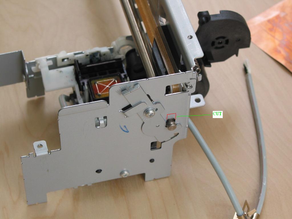
Right
side lever
1024x768px
24b 65.76KB
First I removed the lever from the frame and cut both the frame and lever:
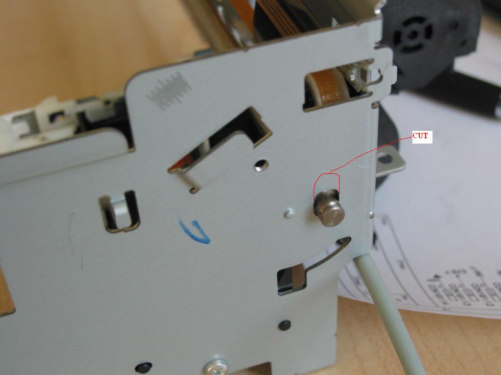
Side
Cut
1024x768px
24b 53.24KB
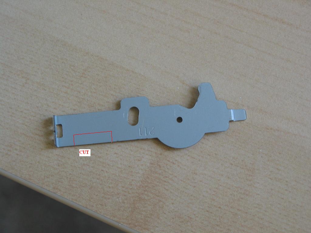
Lever
Cut
1024x768px
24b 77.67KB
I didn't need to do anything for the left side since the adjustment was in the range of the lever:
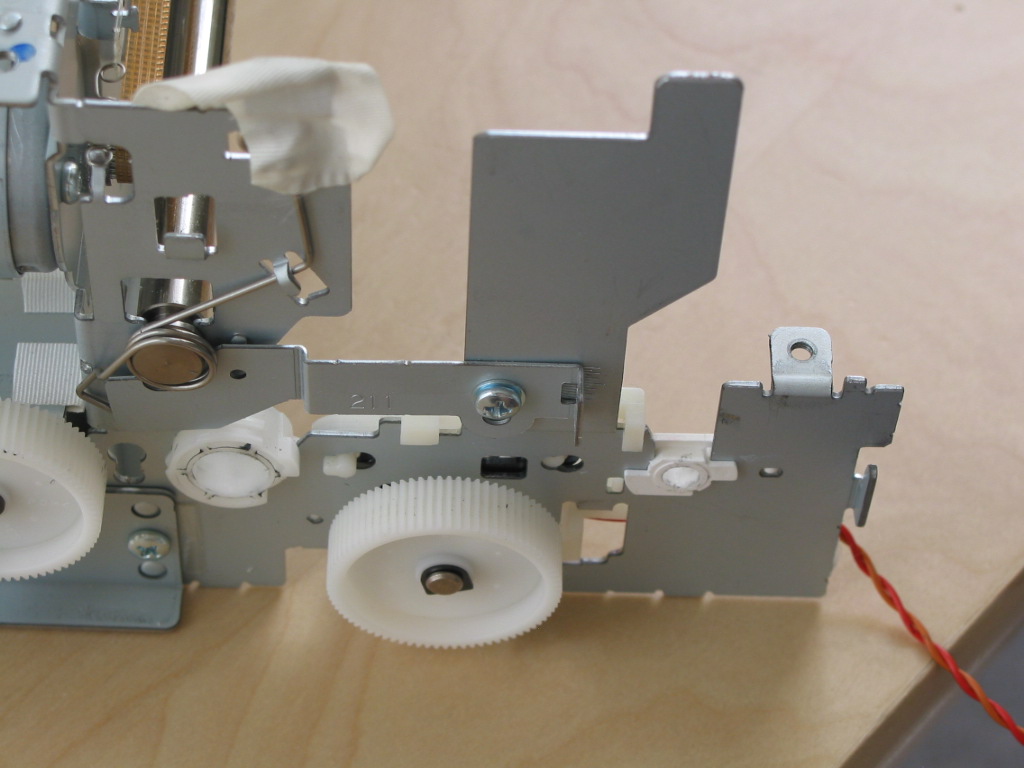
Leftside
Lever
1024x768px
24b 141.13KB
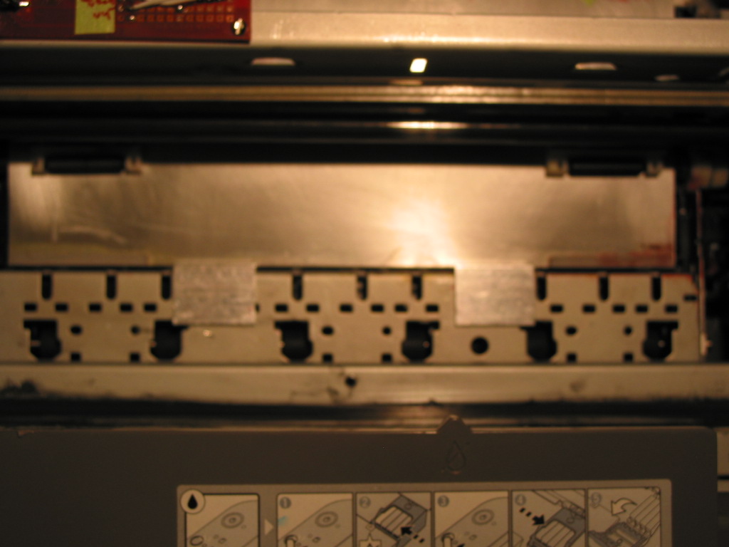
The resulting tilted head pad is shown here:
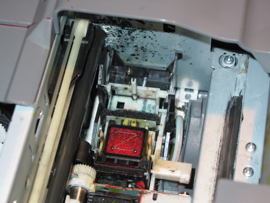
Repositioned
head pad
1024x768px
24b 224.65KB
I removed all the "pizza" wheels on the printer. The pressure rollers also needed to be modified. I removed all of them including their springs and cut one of them in two to use half for the left and half for the right side. In this way, I enlarged the printable PCB area. The modified pressure roller is mounted on a piece of 1/16” PCB which is used as a spring.
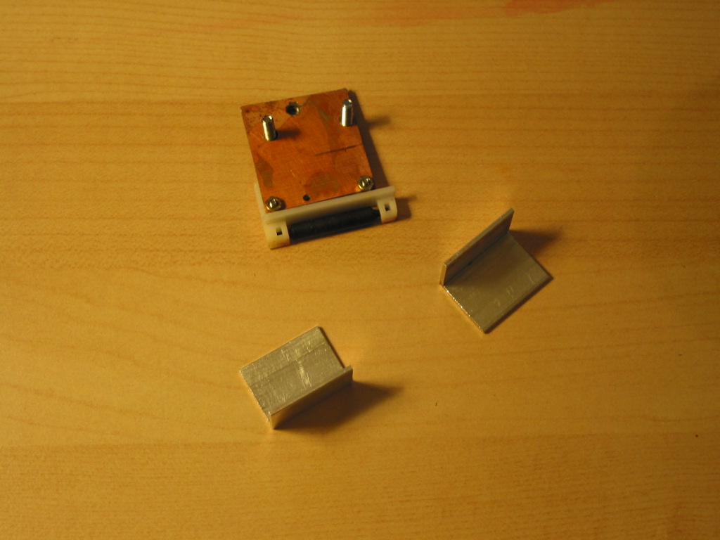
Pressure
roller
1024x768px
24b 156KB
These pressure rollers are finally mounted on a corner aluminum profile and assembled onto the rear frame.
Rear
View
1024x768px
24b 194.65KB
You can see them coming through the front in this photo:
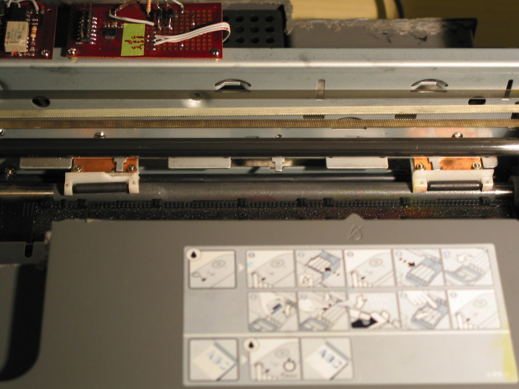
Assembled
pressure roller
1024x768px
24b 182.66KB
This next photo:
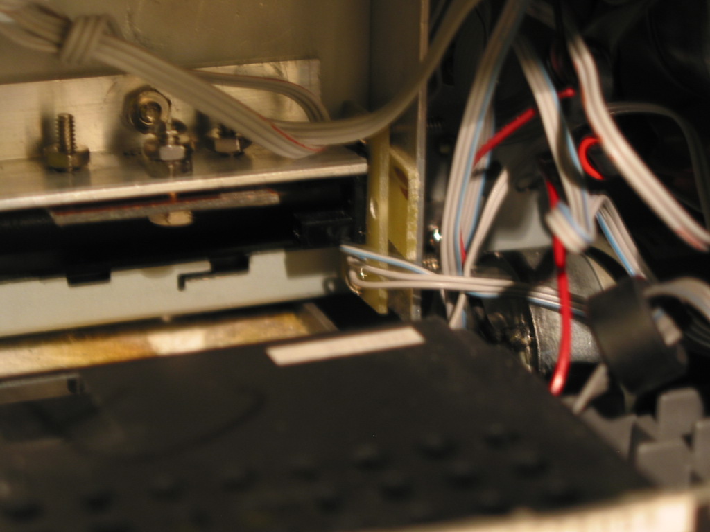
Tray
slot detector assembly
1024x768px
24b 147.52KB
shows an optical slot sensor at the right side that was used as a paper end sensor before. Now this sensor is connected to the paper emulator to detect the slot on the tray
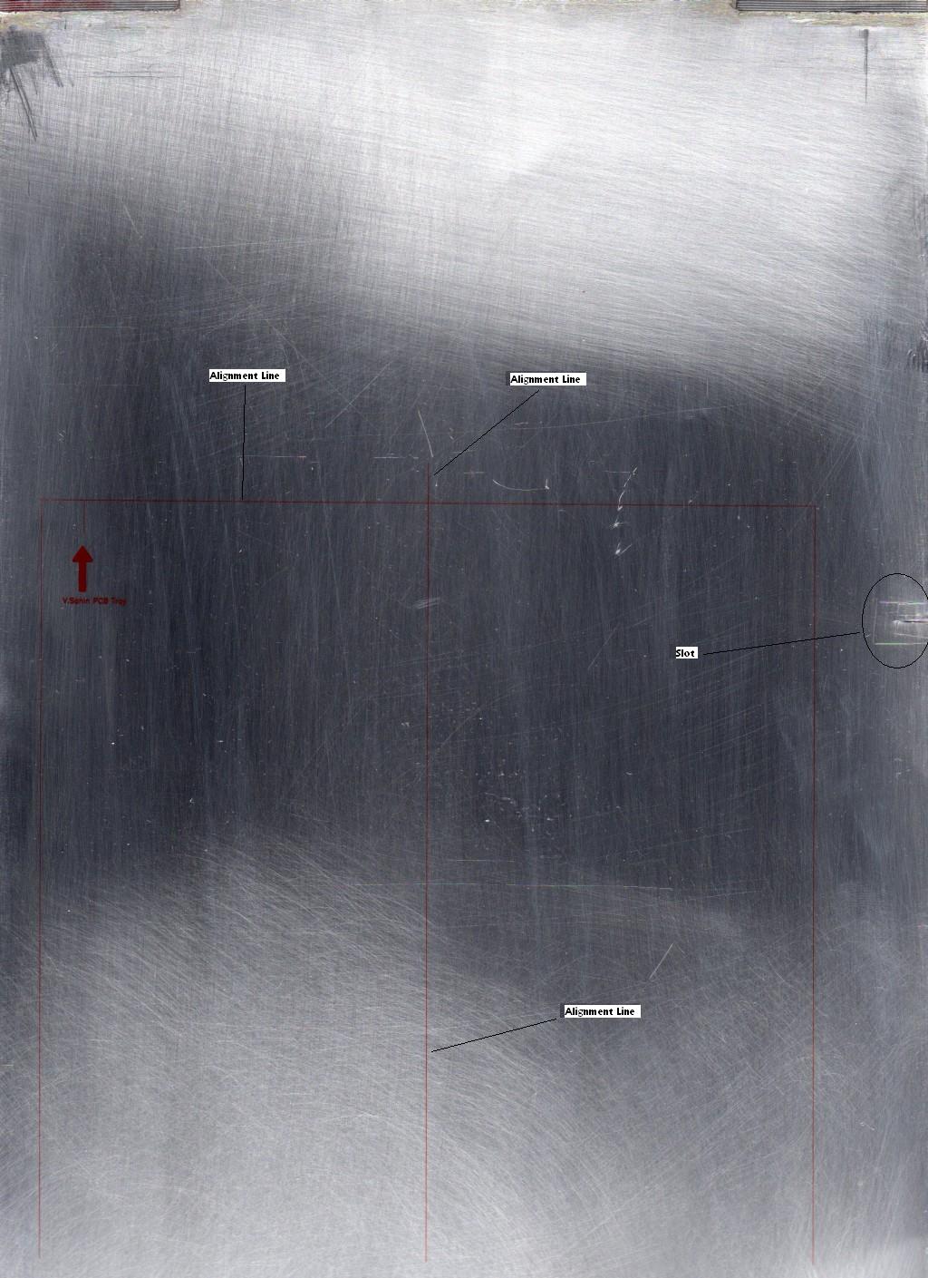
Tray
Slot
1024x1409px
24b 179KB
I have used 0.01” (0.25mm) thick aluminum sheet as a tray
Tray front
1024x768px 24b 134.60 KB
To align the tray I have used a piece of 2 aluminum corner profile
Tray
home
position
adjuster
1024x768px
24b 156KB
Tilting the head also requires some plastic to be cut away on the body of the printer
Cut Plastics
1024x768px 24b 140.72 KB
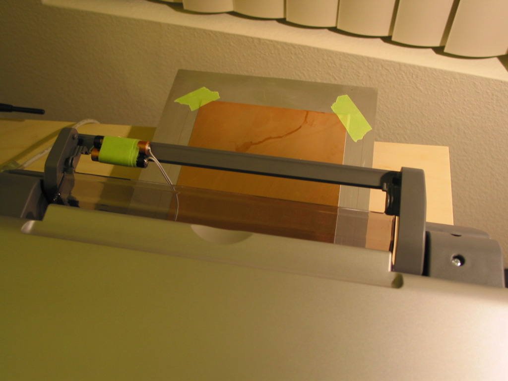
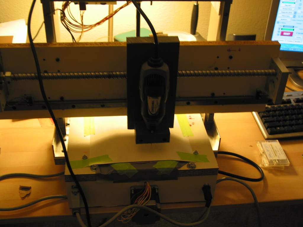
Now, mechanical modifications and electronics are completed and ready, it is time to do some printing.
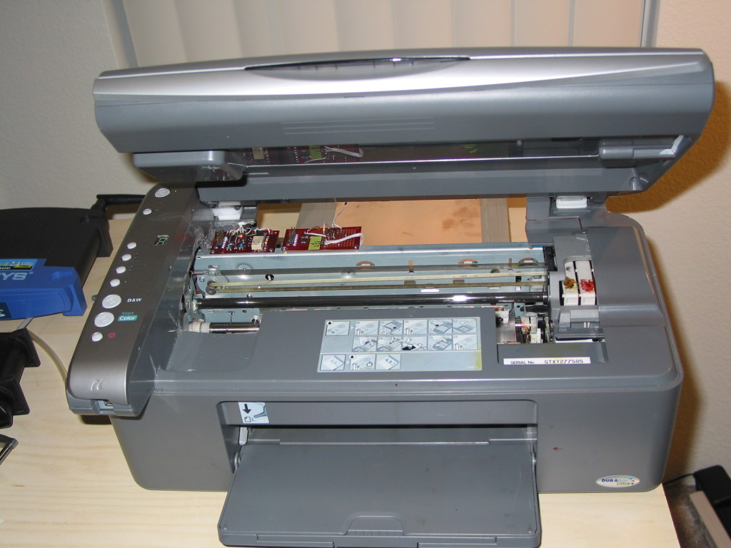
Completed assembly with scanner
1024x768px 24b 184.08 KB
Copper clad board must be clean. Here are the cleaning steps,
Other cleaning methods may used as long as you are sure that the PCB is free of dust and grease.
Handle the PCB carefully to a flat surface since ink is still wet. Wait a while.
Double side PCB printing:
If you need to make solder resist printing use the above procedure and repeat it several times.
Instead of aligning board holes via transparency method sometimes I am using reference drill points at the corners of the PCB
Sample print on tray
1024x768px 24b 316.33 KB
The drill size needs to be very small (I am using 0.0135” 0.34mm carbide bit) to minimize the alignment error. Using these reference holes I am drawing a line till edge of the board using sharp razor and matching it to the lines on the tray. I didn't decide yet which method is the best but later is easier.
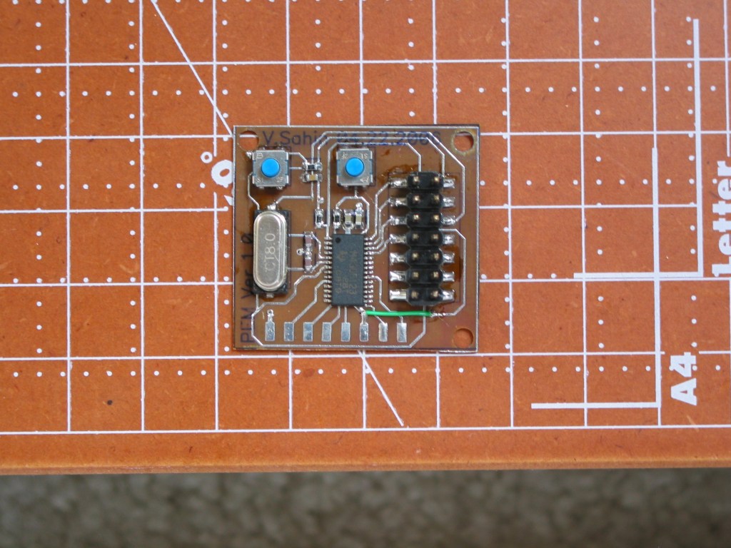
Sample of printed board and populated board are shown
under http://groups.yahoo.com/group/Homebrew_PCBs_Archives/files/Volkan%20Epson%20Inkjet%20PCB/
Print Head Pad
1024x768px 24b 167.81 KB
1st_trial
1024x768px 24b 92.56 KB
Printer and tray
1024x768px 24b 130.89 KB
PCB Solder Sample
1024x768px 24b 258.10 KB
Completed Sample
1024x768px 24b 179.73 KB
PCB Drill
1024x768px 24b 175.46 KB
See also:
http://www.etm.gen.tr Volkan bey,+
yazıcılar hakkında çalışmalarınızı taktir ediyorum
biz yumurta damgalama makinesi yapmak istiyoruz.
bize bu konuda yardımcı olurmusunuz
Questions:
Dear Volkan, could you please post pictures of where to get xenc0/1, yenc0/1 and PDETECT? I´d also like to know what are the voltage levels of xenc and yenc. I´m planning to buy a C110/C120 and use AVR/8051 to spy encoder signals and drive a flatbed with PCB resting on it. I bought a used C65, expecting to spy the step/dir signals sent to stepper controller (Allegro A6628SEDT), but it is custom chip made for Epson, and Allegro can´t reveal details. Problem is I fried the printer with small short-circuit while measuring signals. Stupid me... Thanks!
http://www.hack247.co.uk/2006/08/15/diy-pcb-printer/+
Question for Volkan Sahin: What kind of file did you use to print resist? Was it a paint, coral or cad? Some body needs a consultant for printing using Roland printer which uses epson print head. contact me.
Thanks
Sharma
Comments:
| file: /Techref/pcb/etch/cx4200-vs.htm, 41KB, , updated: 2016/11/12 13:47, local time: 2025/9/5 08:18,
216.73.216.146,10-1-227-87:LOG IN
|
| ©2025 These pages are served without commercial sponsorship. (No popup ads, etc...).Bandwidth abuse increases hosting cost forcing sponsorship or shutdown. This server aggressively defends against automated copying for any reason including offline viewing, duplication, etc... Please respect this requirement and DO NOT RIP THIS SITE. Questions? <A HREF="http://www.massmind.org/Techref/pcb/etch/cx4200-vs.htm"> CX4200, Direct InkJet, PCB Resist, Printing Modifications By Volkan Sahin</A> |
| Did you find what you needed? |
Welcome to massmind.org! |
Welcome to www.massmind.org! |
.