next up previous contents
Next: Computers and Device Interconnection Up: Data Acquisition and Process Previous: Time-to-Digital Conversion

Problems

  1. Design an inverting op-amp circuit that has potentiometers for gain and offset.
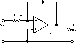
  2. Assuming that the diode shown in the circuit below exactly follows the equation with  A and  mV, sketch versus over the input range -2 V to +2 V. Show the scale on both axes.

     
    Figure 8.10: Operational amplifier with diode in feedback.

  3. Using two 1020-type DACs and two op-amps, design a circuit whose analog output is proportional to the product of two digital numbers.
  4. How many comparators are needed to build an 8-bit flash encoder?
  5. Using a TDC, devise an experiment and show a complete block diagram of a laboratory system to determine the speed of a bullet.
  6. Consider the bad design of the synchronous counter shown below.

    1. What must the JK inputs of the first flip-flop be connected to for the circuit to ``count''?
    2. What must the SR inputs be connected to for the flip-flop output to be well defined?
    3. Determine the truth table and decimal output for the synchronous counter.
    1. Using clocked D-latchs, design a divide-by-4 ripple through counter.
    2. Using clocked JK flip-flops, design a divide-by-4 synchronous counter.
    3. For the synchrnonous divide-by-4 up counter, add appropriate gating so that it may be made to count down by using a mode control signal.
    1. In block diagram form, draw the simplest circuit that can multiplex 16 parallel lines, transmit serially and then demultiplex back into 16 lines. You should build your multiplexer and demultiplexer using parallel-to-serial and serial-to-parallel shift registers, and anything else you think you need.
    2. How may lines between the multiplexer and demultiplexer are needed?
  7. Prepare a comparison table of the three different types of ADCs presented in class. Take into account complexity, resolution, accuracy and speed.
  8. An ideal TTL buffer produces an output of either 0 V or 5 V for input voltages of 0 V and > 0 V respectively. Using ideal TTL buffers and ideal op-amps, design a 4-bit digital-to-analog converter that can produce voltages in the range of 0 to 5 V.
  9. A ramp signal generator is a useful device that gives an output voltage that increases in fixed steps with increasing time. Design a ramp signal generator circuit using 4-bit binary counters and an 8-bit DAC.


next up previous contents
Next: Computers and Device Interconnection Up: Data Acquisition and Process Previous: Time-to-Digital Conversion

Doug Gingrich
Tue Jul 13 16:55:15 EDT 1999