Tools which are necessary to adjust Tools which are necessary to adjust
Procedure of the adjustment
 The adjustment preparation The adjustment preparation
When using the IC sockets, remove the ICs(IC1 to IC10) from the sockets.
(Because the IC breaks when there is a mistake in the wiring, it is for the safety).
Confirm sufficiently about whether there is not a solder-bridge (contacting the terminal or the wiring in the neighborhood with solder) because the wiring is small.
As for the parts such as the capacitors, the diodes, the transistors which have the polarity, confirm whether or not the mounting is right.
The confirmation of the power supply voltage
Connect the power supply.
Make the circuit tester the voltage measurement mode and connect the negative lead line with the grounding and measure the following voltages with the positive lead line. In all voltage measurement after this, the negative reed connects with the grounding.
When the +5 V line voltage isn't over, because to short-circuit is thought of, switch off the power supply at once.
 | The +5 V power supply voltage |
| The 24th pin of IC1 |
| The 24th pin of IC2 |
| The 14th pin of IC3 |
| The 4th pin of IC4 |
| The 5th pin of IC5 |
| The 14th pin of IC6 |
| The 4th pin of IC7 |
| The 14th pin of IC8 |
| The 14th pin of IC9 |
| The 14th pin of IC10 |
If the confirmation of the voltage ends, removes the power supply once and mount the ICs(IC1 to IC10).
Don't attache or remove the ICs as it turned on the power.The ICs have broken.
Attach the ICs after touching the body of the computer and so on and missing the static electricity from your body because it is weak about the static electricity. To become sensitive extremely isn't necessary but the IC breaks when doing improperly.
If mount of the ICs ends, turn on the power again.
The confirmation of the phase comparison frequency
To confirm from the initialization circuit be the procedure but because to confirm that the initialization circuit works is terrible. So, confirm the phase comparison frequency first.
If the phase comparison frequency is over right, the initialization circuit is working normally.
The phase comparison frequency is output by the 13rd pin of IC11(MB87014A).
I connected attenuate wire with the 13rd pin of IC11 directly and measured the frequency with the frequency counter.
I think that the one which installed the 0.5-mm line in the side of the component at fr of the component mounting figure is easy to measure.
Because it understood from behind, I changed the pattern drawing.
It is OK if 2KHz comes out as the phase comparison frequency.
 When not working normally When not working normally
When 2KHz doesn't come out, the initialization circuit or the crystal oscillation circuit must be confirmed.
 The crystal oscillation circuit The crystal oscillation circuit
Confirm solder-bridge, solder-loose (solder isn't stuck right) by the watching because the crystal oscillation circuit is only the wiring. If the 2-MHz frequency is over to the 2nd pin of IC11, the crystal oscillator is working.
The initialization circuit
The confirmation of the initialization circuit is troublesome. The initialization circuit works only for the about 20 milliseconds in case of the turning on.
First, confirm solder-bridge, solder-loose by the watching.
Remove IC7. By removing IC7, the initialization circuit works continuously.
Confirm that the multi-vibrator works in this condition.
Connect the frequency counter with the 8th pin of IC8. If the frequency from about 600 Hz to 1000 Hz is over, the operation of the multi-vibrator is OK. Because this circuit sometimes doesn't work with the characteristic of the IC, when not oscillating normally, it attempts to change the kind of the IC. 7400 rather than 74LS00. It isn't possible to use 74HC00.
As for me, the thinking doesn't hit the thing except the operation confirmation of the multi-vibrator. The IC broke?
Search by the symptom.
The adjustment of the phase comparison frequency
Adjust the phase comparison frequency in VC1.
Because it is the crystal oscillator, the frequency changes hardly. It is the fine control.
The adjustment of the output buffer
Adjust the resonant frequency of the output buffer in L2.
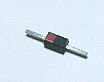
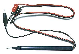
I introduce the simple-type high frequency detector. It connects with the circuit tester and it uses.
Adjust L2 to connect this detector with the output terminal of the PLL circuit and for the voltage of the tester to become the highest.(The about 3-V voltage is over).

 The simple high frequency detector The simple high frequency detector
|