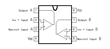
Data of the TL082 operational amplifier Data of the TL082 operational amplifier
As for TL082, the two operational amplifiers are enclosed with the one package.
PIN connections (Top View)
 MAXMUM RATINGS MAXMUM RATINGS
| Rating | Symbol | Value | Unit |
| Supply Voltage |
VCC
VEE |
+18
-18 | V |
| Differential Input Voltage | VID | ±30 | V |
| Input Voltage Range(Note 1) | VIDR | ±15 | V |
| Output Short Circuit Duration(Note 2) | tSC | Continuous |
|
Power Dissipation
(Plastic Package) |
PD
1/8JA |
680
10 |
mW
mW/°C |
| Operating Ambient Temperature Rage | TA | 0 - +70 | °C |
| Storage Temperature Range | Tstg | -65 - +150 | °C |
|
| Note | 1. | The magnitude of the input voltage must not exceed the magnitude of the supply voltage or 15V, whichever is less. |
| 2. | The output may be shorted to ground or either supply. Temperature and/or supply voltages must be limited to ensure that power dissipation ratings are not exceeded. |
TL082 is the IC which was developed by the Texas Instruments,inc..
The second source is produced from the following maker.
| Maker | Device Name |
| NEC | uPC4082 |
| JRC | NJM082 |
| Panasonic | AN1082 |
| Hitachi | HA17082P |
| Fujitsu | MB47082 |
| Motorola | TL082 |
| Tomson | TDB0082 |
| EXAR | XR-082 |
| Sanyo | LA6082D/S |
| Shape | IR9082 |
Triangular wave oscillator
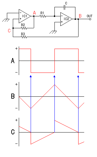 The triangular wave oscillator is composed of the Schmitt circuit and the integration circuit which is being explained below. The triangular wave oscillator is composed of the Schmitt circuit and the integration circuit which is being explained below.
IC1 is the Schmitt circuit and IC2 is the integration circuit.
In case of the turning on, the output (the A point) of the Schmitt circuit becomes the positive or negative saturated voltage.
In the following explanation, the output makes the positive saturated voltage.
The electric current flows through the capacitor C through the resistor R1 when the A point becomes positive. When the electric charge begins to store up in the capacitor, voltage of the both edges of the capacitor begins to go up. Because the negative input terminal of IC2 is approximately 0 V, the voltage of the output (the B point) of the integration circuit falls gradually.
The positive input terminal voltage (the C point) of IC1 is the one to have broken up the voltage difference between the A point and the B point with the resistors R2 and R3.
Voltage of the C point, too, goes down when voltage of the B point begins to go down.(The fall percentage depends on the ratio of the resistors R2 and R3).
When the voltage of the C point falls below 0 V, the voltage of the output (the A point) of the Schmitt circuit changes into the minus rapidly. For the voltage of the C point to fall below 0 V, the condition of R2>R3 is necessary. Then, the flow of the electric current to the capacitor C reverses and the electric current flows through the direction of the A point through the resistor R1.
With this, the voltage of the B point rises gradually.
At this time, the C point changes into the direction of the negative and rises as the B point rises.(The rise percentage depends on the ratio of the resistors R2 and R3).
When the voltage of the C point exceeds 0 V, the output (the A point) of the Schmitt circuit changes into the plus rapidly. This changes the B point to the direction of the negative. The condition of R2>R3 is necessary for the voltage of the C point to exceed 0 V, too.
After that, it repeats this operation, the square wave is output by the A point and the triangular waveform is output by the B point. |
Basis of the operational amplifier
The operational amplifier is the amplifier with the very big voltage gain.
In case of TL082 to be using this time, at the specification, the voltage gain becomes 150V/mV. It is the 15-V output in 0.1 mV of the input. To say becomes 150,000 times of gain. In case of the operational amplifier, the value of the voltage gain doesn't have the relation too much. Anyway, the fact that the voltage gain is big is important.
 The Inverting Gain amplification The Inverting Gain amplification
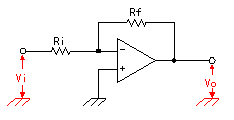 There are positive input and negative input in the operational amplifier. There are positive input and negative input in the operational amplifier.
When voltage of the negative input terminal goes up, the output falls. That is, when using the negative input terminal, it becomes the inverting gain amplification.
The voltage gain can be calculated by the following formula.
G = Vo/Vi = -(Rf/Ri)
The voltage gain(G) in case of Rf=100K-ohm, Ri=10K-ohm becomes by 10 times.
Because the voltage gain of the operational amplifier is very big, the voltage of the negative input terminal is approximately 0 V.(Actually, it is tens of uV).
Because it is, the input impedance (the resistance of the alternating current) of the circuit becomes Ri almost.
Also, the input electric current to the operational amplifier itself flows hardly. |
The Noninverting Gain amplification
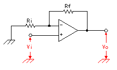 It is the way of appling the input signal to the positive input terminal. The output power, too, rises when input voltage goes up. It is the way of appling the input signal to the positive input terminal. The output power, too, rises when input voltage goes up.
The voltage gain can be calculated by the following formula.
G = Vo/Vi = 1+(Rf/Ri)
The voltage gain(G) in case of Rf=100K-ohm, Ri=10K-ohm becomes by 11 times.
|
The Schmitt circuit
 Of the output the Schmitt circuit returns at the positive terminal of the input. The amplification of the operational amplifier is accelerated by this. Of the output the Schmitt circuit returns at the positive terminal of the input. The amplification of the operational amplifier is accelerated by this.
The output becomes the positive or negative saturated voltage(It is the voltage of the power supply almost).
Because the negative input terminal is the grounding (0V), when the input voltage exceeds a few 0 V in positive, the output voltage becomes the positive saturated voltage. When the input falls below a few 0 V, the output voltage becomes the negative saturated voltage.
It is the way of using of the operational amplifier transforming. This time, I use this circuit. |
Integration circuit by the operational amplifier
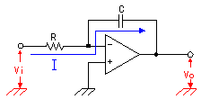 It is the circuit which replaced the part of the resistor for the return of the inverting gain amplification with capacitor. It is the circuit which replaced the part of the resistor for the return of the inverting gain amplification with capacitor.
Because the input voltage of the operational amplifier itself is approximately 0 V, the electric current (I) which flows through the resistor R is calculated by the following formula.
I = Vi/R
Because the input electric current flows through the operational amplifier hardly, this electric current flows through capacitor(C) just as it is.
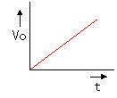
In case of being the voltage with constant Vi, the electric current which flows into the capacitor, too, becomes constant. Because it is, the voltage of the both edges of capacitor changes straight in the time and the output voltage (Vo) changes straight.
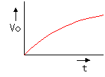
As for the integration circuit which is composed of the resistor and capacitor, the electric current which flows into capacitor changes in the time. Therefore, the output voltage doesn't change straight. Because the electric current is constant at the integration circuit which used the operational amplifier, it changes straight.
The figure below is the one to have compared the voltage of the integration circuit only of the CR and which used the operational amplifier.
When the electric current flows like the blue line of the circuit diagram above, Vo falls in the time.
|
|