The change of the voltage and the current by the load change The change of the voltage and the current by the load change
| When making the load resistance which connects with the output small, there is a point where the output voltage begins to fall. At the circuit which was made this time, the output voltage begins to fall at less than 100-ohm in the load resistance. I think that this is the one by the limitation on the input electric current(In the calculation, it is 1.3-A). |
The electric power change by the load change
The figure above shows the change of the input/output electric power and the efficiency when making the load resistance small. In case of less than 100-ohm resistance, the output power is rising gradually. However, because the output voltage is falling, it isn't possible to use as the practical use.
The efficiency in the practical use range is from 70% to about 80%. The loss in the converter(Input power - Output power) is about 2 W. Even if the load changes, this value isn't changing too much. Because it is, when the output power becomes small, the efficiency falls. |
The change of the voltage and the current by the input voltage drop
I measured the change of the output voltage and the current when dropping the input voltage.
When the load resistance is 100-ohm, it is the upper limit of the converter ability. Therefore, when dropping the input voltage, the output voltage begins to fall.
When the load resistance is 200-ohm, the input electric current is not the limit value. Therefore, even if it lowers the input voltage to about 7 V, the output voltage maintains 30 V. When the output power increases, the input electric current increases. When the input voltage is 7 V at 200-ohm in the load, the input electric current becomes about 1 A and is the limit of the ability. When making the voltage below it, the output voltage begins to fall. |
The electric power change by the input voltage drop
The figure above shows the change of the output power and the efficiency when dropping the input voltage.
When the load resistance is 100-ohm, as the input voltage falls, the output power begins to fall.
When the load resistance is 200-ohm, you find that the constant output power is supplied in about 7 V. The input electric power doesn't change too much and the loss of the converter is about 2 W. |
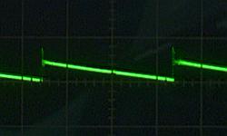
The ripple voltage
The photograph above is the wave form of the ripple voltage which appears in the output in case of the no-load. The voltage is about 30 mVp-p. It becomes 0.1% of the ripple voltages because the output voltage is 30 V.
This ripple voltage passes away almost when the electric current flows through the load and the output voltage becomes the pure DC voltage. At the circuit this time, the secondary filter is used. I think that the filter operation of the coil (L2) of the secondary filter works when the electric current flows through the load and the flow of the ripple current is prevented. |
|