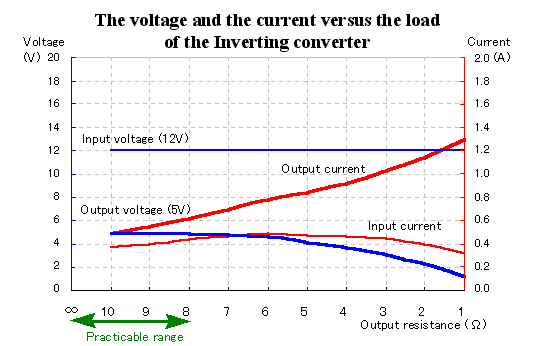
With the following chart, I am picturing the output voltage as the positive voltage but the fact is the negative voltage.
 The change of the voltage and the current by the load change The change of the voltage and the current by the load change

When making the load resistance which connects with the output small, there is a point where the output voltage begins to fall. At the circuit which was made this time, the output voltage begins to fall at less than 8-ohm in the load resistance.
The circuit composition is the same as the step down converter approximately but the practicable range becomes narrow. As for the difference on the circuit composition, the value of the coil (L1) is different. The 250-ÁH is used at the step down and the 72-ÁH is used at the inverting. I thought that the practicable range became narrow because the energy which is stored up at the coil was little but it is not right.
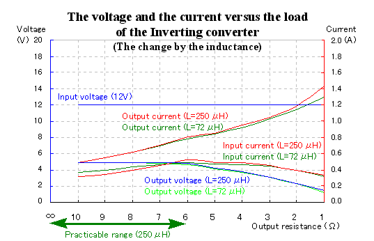
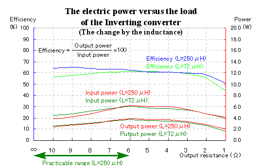
The performance measurement result when making the coil (L1) in the inverting converter 250-ÁH is shown below.
|

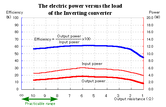
 The electric power change by the load change The electric power change by the load change

The figure above shows the change of the input/output electric power and the efficiency when making the load resistance small. In case of less than 8-ohm resistance, the output power is rather increasing. However, because the output voltage is falling, it isn't possible to use.
It isn't good to be efficient because the loss in the converter(Input power - Output power) is about 2 W but the output power is small. |

 The change by the inductance The change by the inductance


I measured the characteristic when I change the inductance of the coil (L1) into 250-ÁH. There is not a big change in the characteristic. The practicable range when lowering the output resistance becomes rather wide. However, it doesn't become the characteristic like the step down converter.
In case of the step down converter, the input electric power is directly applied to the output power when the regulator is ON. However, in case of the inverting converter, it is the structure which outputs only the energy which is stored up at the coil (L1). I thought that the limit value with the output power rose if I made the inductance value big. However, there was not a big change. This value seems to be the limit.
I changed the value of the timing capacitor from 1500 pF to 470 pF and made the switching frequency rise but I am not making the graph. In this case, the characteristic changed hardly too. Rather, the characteristic became bad a little.(Range of the measurement error)
I think that it does the influences such as the loss of the diode. |

 The ripple voltage The ripple voltage
The photograph above is the wave form of the ripple voltage which appears in the output in case of the no-load. The voltage is about 10 mVp-p. It becomes 0.2% of the ripple voltages because the output voltage is 5 V.
Because the output voltage in case of the inverting converter is the negative voltage, the top and the bottom of the wave form becomes opposite compared with the step-up or step-down converter.
This ripple voltage passes away almost when the electric current flows through the load and the output voltage becomes the pure DC voltage. At the circuit this time, the secondary filter is used. I think that the filter operation of the coil (L2) of the secondary filter works when the electric current flows through the load and the flow of the ripple current is prevented. |
 |