The components explanation
of switching regulator(2)
(MC34063A)
 This is the switching regulator IC of the Motorola. This is the switching regulator IC of the Motorola.The operation frequency is possible to about 200 kHz and the switching electric current can be handled in 1.5 A. By changing the circuit to install outside, it is possible for the converter to be worked in Step-up, Step-down and Inverting. It doesn't install the heatsink. It radiates from the body of the IC and to the print pattern with the heat conduction from the pin. Because it is, you consider the radiation as well as the current-carrying capacity as the print pattern and make it the thick pattern. To improve the thermal efficiency, the IC is mounted on the printed board directly. 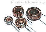 The coil of L1 stores up the electrical energy from the input and slips the energy by the switching operation of the regulator to output. 250µH, 2A is used in the step down converter. 125µH, 2A is used in the step up converter. 72µH, 2A is used in the inverting converter. 25µH, 2A is used for the secondary filter. The toroidal coil is the coil with the good efficiency because little leakage of the magnetic flux occurs. The coil of L2 is the coil of the secondary filter to reduce the ripple of the output. 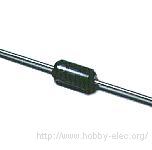 This diode applies the flow of the electric current which the switching operation of the regulator changes only to the side of the output. Because the switching operation is high-speed comparatively, as the diode, you must use the Shottky barrier diode or the first recovery diode with the short reverse recovery time. As the current-carrying capacity, it uses more than 1.5 times of ones of the output current. The diode which was used this time is ERB81-004(VRRM=40V, IO=1.7A) which is made by Fuji Electric. 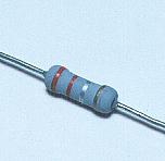 This is the resistor to detect the input electric current, being inserted in the input circuit in series. I am using 0.22 ohm for the resistor with the circuit this time. The consumption electric power of the resistor becomes the following. P = VI = V x V/R = (0.3V)2/0.22ohm = 0.41W I am using the resistor with the 1-W rated power.  This is the fixed resistor to be using to adjust the output voltage. You decide the value of this resistor by the voltage control range by the variable resistor(VR1). Few electric currents which flow through this resistor, so, it is OK that the rated power of the resistor is the 1/8-W one. 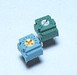 This resistor is used for the adjustment of the output voltage. Few electric currents which flow through this resistor, so, I am using the small variable resistor. 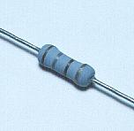 This is the resistor to limit the collector electric current of the drive transistor which drives the main switching transistor. This resistor is used in case of the step up converter. In case of the step up converter, the switching transistor collector voltage change is big. Because it is, it is controlling the transistor for the drive at the comparatively stable input voltage. (It is mentioned to the sample circuit. The reason is my imagination.) The electric current which flows through the collector when the drive transistor is in the ON condition is as follows.
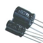 You use the capacitor of few ESR(Equivalent Series Resistance) for the ripple filter capacitor of the output. The capacitor has the inductance and the resistance as well as the capacitance. This resistance is the ESR. When the value of the ESR is big, it generates heat with the electric current which flows through the capacitor. The big electric current flows through the capacitor to use with the ripple filter circuit of the switching regulator. Because it is, the capacitor which has the big ESR is heated. 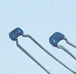 I used the multilayer ceramic capacitor for the timing capacitor of the oscillation circuit. You use the one which is done by the temperature compensating for this capacitor. The change of the capacity by the temperature is few types. You can use polystyrene film capacitor where little capacity change by the temperature occurs, too. 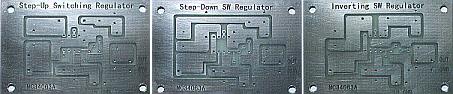 I used the positive exposure printed board. The size of the printed board is 75mm x 50mm. 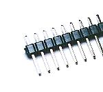 This is the terminal to connect the cable of the input and the output. It is not necessary to use the one of this shape. Also, if connecting the wire with direct to the printed board, it is not necessary to use this terminal. 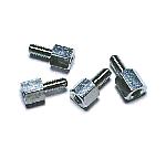 I use this to install the printed board to the case. There is not necessity of the metal. |