Performance evaluation
of DC/AC inverter (2)
|
I will report the performance evaluation result of the inverter which was made this time. As the test bed, a battery for the car is used for the power supply and bulbs are used for the load. The internal resistance of the battery is very low and the big electric current (more over 100A) flows through the terminal when short-circuiting. So, you must not make short-circuit absolutely.  I measured the input voltage, the input electric current, the output voltage when changing the wattage of the bulb of the load. The output voltage falls when making a load big. The consumption electric power of the bulb changes with the voltage. So, I am converting to the consumption electric power according to the change of the voltage. In this case, I assume that the resistance value of the bulb doesn't change. However, the resistance value of the bulb changes with the consumption electric power. So, the result has errors by this conversion. Also, the voltage and the current are not sine wave. The result has more errors. However, I judged that these errors didn't have a big influence on the result.
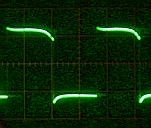
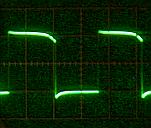
 I measured the temperature rise of the FET when an inverter is used in the continuous duty with the maximum load. The measurement place is the heat sink which the FETs are put on. I put a thermocouple thermometer to this part.  The output of this inverter is a square wave. When the load becomes big, the wave from of the output voltage will be slightly changed by the nature of a coil of the transformer. There is to slightly change in the wave from of the rising edge and the falling edge. However, I think that it is permitted to say that it is changing hardly.
|