
 Voltage comparator (LM319) Voltage comparator (LM319)
It compares the input signal level and the reference voltage and it makes the output ON at the time above the reference voltage.
The circuit this time is using the four voltage comparators to have the detection with the 4 levels.
Because the two voltage comparators are housed in the one package, I am using two pieces of the IC.
At the circuit this time, I used LM319. It is little in the number of the parts when using the LM339 that the four voltage comparators are enclosed with the 1 package. The pin arrangement of LM339 is different from LM319. So, when using LM339, the pattern drawing must be changed.
2 input NAND gate (74HC00)
I used the 2 input NAND gate IC to choose the one output of the four voltage comparators.
Because the four 2 input NAND gates are housed in the one package, I am using one piece of the IC.
Relay drive buffer (74LS07)
 This is the open collector-type buffer circuit. The operating voltage of IC itself is +5 V. However, because the collector circuit of the output transistor becomes open, the relay which drives at +12 V can be controlled. This is the open collector-type buffer circuit. The operating voltage of IC itself is +5 V. However, because the collector circuit of the output transistor becomes open, the relay which drives at +12 V can be controlled.
In case of 74LS07, the 40-mA electric current can be applied to the output transistor.
The six buffer circuits are housed in the one package.
3 terminal regulator (78L05)
I used the 3 terminal regulator to make the +5V voltage with the +12V power supply.
The 100-mA electric current can be gotten.
Transistor for the signal amplification (2SC1815)
I used the general transistor for the small signal amplification to amplify the input signal.
Diode for the signal rectification (1S1855)
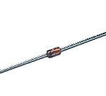
Being rectifying the half wave with the diode to change the input signal into the DC voltage. I used the diode for the small signal.
Zener diode (RD-5A)
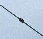 Generally, it uses the Zener diode to make the voltage be stable. This time, I am using it to protect the IC from the high voltage. The electric current begins to flow through RD-5 A when adding more than +5 V to the opposite direction. The permission electric power of the diode is 250 mW. So, the maximum of 50-mA electric current can be passed. Generally, it uses the Zener diode to make the voltage be stable. This time, I am using it to protect the IC from the high voltage. The electric current begins to flow through RD-5 A when adding more than +5 V to the opposite direction. The permission electric power of the diode is 250 mW. So, the maximum of 50-mA electric current can be passed.
Variable resistor for the reference voltage setting
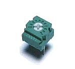
This is the variable resistor to adjust the reference voltage of the voltage comparator. It adjusts according to the level to detect.
This time, I used the resistor of 20K-ohm. The one with the different value doesn't care. However, the electricity consumption increases when the resistance value is small. There is possibility that the electric current which flows through the input of the voltage comparator changes the reference voltage when making the high value.
Relay (G5V-2)
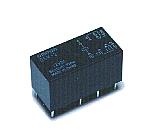 I used the relay to control the lamp outside and so on. I used the relay to control the lamp outside and so on.
I used the one that the drive voltage is DC 12 V .
There are two sets of points of contact.
The specification is shown below respectively.
125V AC : 0.6A
110V DC : 0.6A
30V DC : 2A
Diode for the overvoltage protection
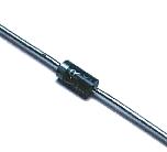
This is the diode to protect the buffer circuit from the voltage which is high comparative-ly which occurs to the coil of the relay at the time of ON/OFF of the relay. This time, I used cheap one of 200V 1A. The occurring voltage depends on the inductance of the coil of the relay.
Light-emitting diode
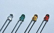 I used the light-emitting diode with the color which is different every level. The 1st level is "Blue", 2nd is "Green", 3rd is "Yellow" and 4th is "Red". I used the light-emitting diode with the color which is different every level. The 1st level is "Blue", 2nd is "Green", 3rd is "Yellow" and 4th is "Red".
The blue LED(Transparent one) which was used this time is the high brightness-type LED. Therefore, I make the value of the resistor for the electric current control big to suppress the light.
Electrolytic capacitor
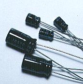
At the amplification circuit of the input signal, these are used for the purpose of the cut of the DC voltage.
At the direct current change circuit, these are used for the leveling of the voltage change.
In the power supply, these are used for the purpose of the removal of the low frequency noise.
Multilayer ceramic capacitor
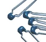
These are used to remove the high frequency noise of the power supply.
Resistor
All used resistors are 1/8 W.
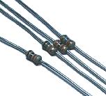
Terminals for the wiring
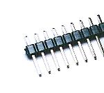
These are used to connect the wire with the circuit outside. When connecting the wiring with the printed board directly, there are not necessary.
I am using to install the resistor to adjust the bias electric current of the signal amplifier, too.
Printed board
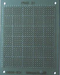
I used the universal board with the 25 x 30 holes. In the interval in the hole, it is the 0.1 inches.
Metallic stud
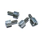
I use this to install the printed board to the case.
|