Gerber file making by EAGLE
|
When making an actual printed circuit board based on the data made from CAD, the data of Gerber form are used in many cases. Gerber data are the data formats which a photograph plotter maker's Gerber Scientific Instrument Company created. All the information (the position of a hole, a size, thickness of a line, etc.) for automating manufacture of a printed circuit board is numerically expressed with Gerber data. Gerber form is standardized as CAD output data of a printed circuit board. The printed circuit board data created by EAGLE are the form only for EAGLE. It is not Gerber form. There are also some companies which accept a printed circuit board by the EAGLE data(*.brd) like OLIMEX in Bulgaria. The data made with EAGLE is convertible for a Gerber file with the following operations. 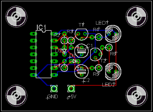 A-stable multivibrator (IC type) introduced by "Let's try" is made into the example in the following explanation. First, open the target project with the control panel of EAGLE, and display a board file. 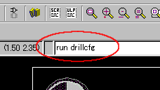 To the beginning Drill Rack file is made. For carrying out this operation, type in "run drillcfg" to a command bar, and push an enter key.  Choose an inch as a unit, and push the OK button. 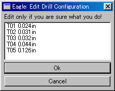 The list of the drill size used now is displayed. On this screen, push the OK button, without doing anything, and progress to the next. 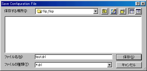 The dialog which saves a Drill Rack file (*. drl) is displayed. You have to save this file in the same folder as a board file (*. brd). The information written to the board file is used in CAM Processor performed next. Therefore, *.drl must be in the same folder.
The list shown in the left is the contents of "test.drl". It is the same as the contents displayed on the previous window.  Choose "CAM" with an icon bar. Thereby, the following dialog of CAM Processor is displayed. 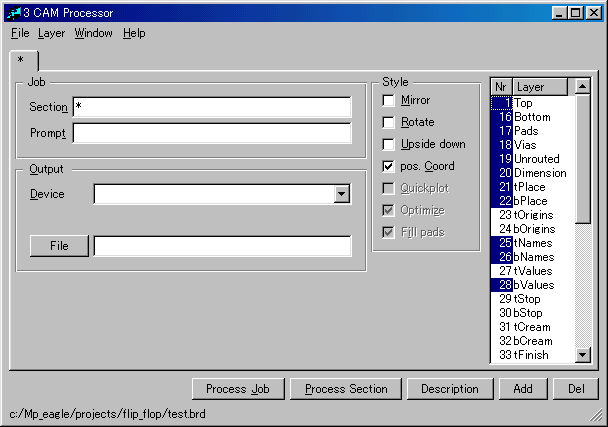 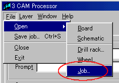 Choose "Open" by the file menu of a CAM Processor dialog, and choose "Job" further. 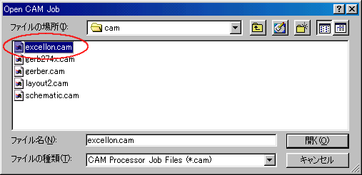 Choose "excellon.cam" from the list displayed, and push the open button. 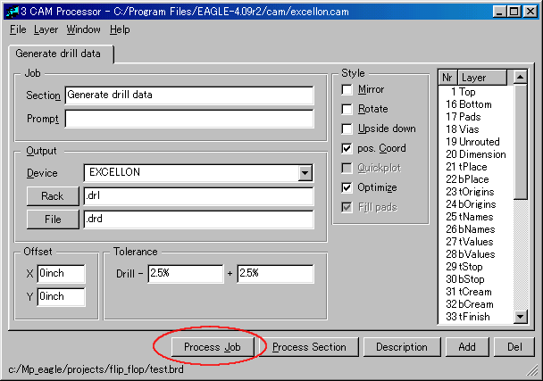 Check the items setup of Generate drill data, and push the "Process Job" button. The setting items are left default when details are not known. The Excellon drill files ( *. drd, *.dri ) are made by this processing.  Choose File -> Open -> Job like creation of Excellon drill files. 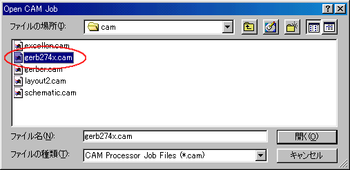 Choose "gerb274x.cam" from the displayed list, and push the open button. As for a Gerber file, EIA standard RS-274 are common. In the plotter control format of GSI (Gerber Scientific Instrument), "gerber.cam" is used maybe. 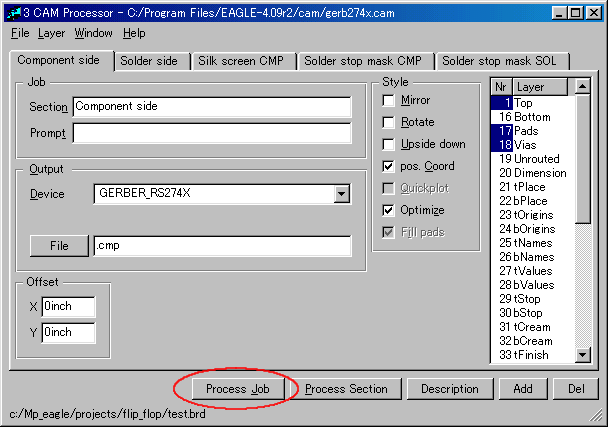 Check the items setup of Generate drill data, and push the "Process Job" button. The setting items are left default when details are not known. The Gerber files ( *.cmp, *.sol, *.plc, *.stc, *.sts, *.gpi ) are made by this processing. The following Gerber files can be made from the above processing.
I have not placed an order for a printed circuit board using these data. Therefore, I cannot advise on fine notes. |