|
On this page, I will explain the PIC16F84A timer specifications .

 Specification of the timer (TMR0) Specification of the timer (TMR0)
The figure above shows the timer (TMR0) and watchdog timer (WDT) block diagram.
Each register under the figure affects the timer setting. The yellow bits are related.
The Prescaler, which is at the center of the figure, can be used for either the TMR0 or WDT. The figure above shows the prescaler connected to TMR0. The PSA bit (bit 3) of the OPTION_REG determines to which of the two the prescaler is connected. The prescaler is a programmable counter whose count ratio is determined by OPTION_REG bits PS0, PS1, PS2 (bits 0, 1, &2). TMR0 is a binary 8 bit counter which can count up to 256. When the counter changes from 255(FFh) to 0(00h) an interrupt overflow occurs and T0IF bit (bit 2) of the INTCON register is set (becomes "1"). The hardware is designed such that when both the GIE (bit 7) and TOIE(bit 5) of the INTCON register are Hi ("1") the interruption occurs and the PC goes to address 004h, to start program operation from there.
A 256 count of TMR0, is sometimes short. For example, when the internal clock is 20MHz, the counter input frequency is 5MHz.(FOSC/4). The period of this clock pulse is the 200ns (1 / 5Mhz = 0.2µsec). So it takes TMR0 51.2µsec (0.2µsec x 256) to overflow. In order to extend this period the prescaler is used.

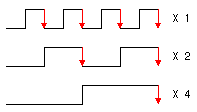
The prescaler can be used to divide the input by 2, 4, 8, 16, 32, 64, 128, or 256. For example, when the prescaler is set to divide by 2, there is 1 output pulse for every 2 pulses which are input to the prescaler. If set to 256, there will be 1 output pulse for every 256 pulses inputted. So, the overflow time of TMR0 can be made longer by setting the value of the prescaler. In the previous example when the prescaler was set to 256, the overflow time becomes 51.2µsec x 256 = 13,107.2µsec (about 13 milliseconds).
The input to timer (TMR0) can be an external clock or the internal clock. To use the external clock, the T0CS bit (bit 6) of the OPTION_REG register and bit 4 of the TRISA register must be set to "1". This will put RA4/T0CKI pin in input mode (TMR0 CLOCK IN). Also, the rising or falling edge transitions of the clock pulse can be selected by the T0SE bit (bit 5) of the OPTION_REG register. For rising edge clear it "0" and for falling edge set it to "1".
At the input to the timer (TMR0) there is a clock synchronizing circuit. When using an external clock, the timing of the rising and falling edges of the clock will not be synchronized with the internal clock. This will upset interrupt timing. This circuit synchronizes the TMR0 input with the internal clock. Synchronization is achieved in a maximum of 2 cycles.
The Watch Dog Timer's (WDT) oscillator is independent from the CPU clock. The WDT time-out is about 18 msec.

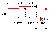
Generally, to prevent a time out condition the WDT must be reset periodically via software using the CLRWDT instruction. If the Timer is not reset before it times out, the CPU will reset forcing it to the address location immediately after power on. The prescaler can be used to extend the time-out period.
In this case, the count values are different from TMR0. The prescaler can be set to eight values 1, 2, 4, 8, 16, 32, 64, or 128. When set to 128, the time-out is the about 2 seconds (18msec x 128 = 2,304msec).
The function of the watchdog timer (WDT) is to prevent incorrect operation of the software. (Run away: It executes instructions which are not part of the program. / Loop: It executes the same part repeatedly.) The WDT function isn't always necessary. If there is a mistake in the program you can usually recognize there is a malfunction by the way it operates ( it doesn't perform the way you expect it to). If the WDT resets the PIC you may not be able to understand what caused the program to malfunction. It may be better not to use the watchdog timer. To stop the operation of the watchdog timer, reset the WDTE bit of the configuration word (2007h) of the program memory to "0".
Basically I don't use the watchdog timer. In that case, the prescaler can be used for the TMR0.
 |