
 PIC PIC
This is PIC16F84A. In case of PIC16F84A, it is possible to use clock frequency upto 20 MHz. The circuit this time, I am using 10-MHz resonator.
78L05
This regulator is used to make the stable power of +5 V.
The maximum output current is 100 mA.
IC socket
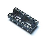
The PIC is mounted after writing a program by programmer. So, the IC socket is necessary.
Resonator
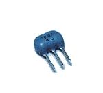
I used 10-MHz resonator. A ceramic vibrator and capacitors for the oscillation are combined inside.
LED
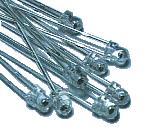
I used red high brightness-type LEDs. Because a 560-ohm resistor is put in series with the LED, the current in lighting-up is about 5 mA.
Switch
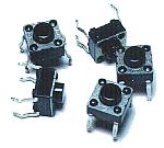
This is the switch to select the blinking pattern of LEDs. It is printed board mounting type and non lock type.
Resistor
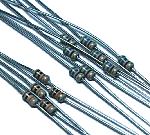
These resistors are used for current control of the LEDs( 560 ohm ) and pull-up of the PIC input terminals( 10K ohm ).
Electrolytic capacitor
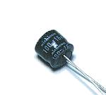
This capacitor is used to be stabilized of the input voltage and to bypass a low frequency noise.
Multilayer ceramic capacitor
These capacitors are used to bypass the high frequency noise of the input and output of the power supply.
Printed board
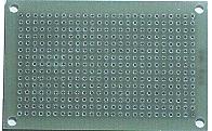
This is an universal printed board with 15 x 25 halls.
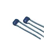
Wiring terminal
This terminal is used to connect a power supply wire.
Stud
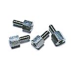
This is used as the leg of the printed board.
|