|
The way of debugging that I do is shown below.
 Preparation Preparation
I debugged by MPLAB. It's better to display the following windows beforehand on the screen.
 Listing file Listing file
Window > Absolute Listing
 SFR ( Special Function Register ) SFR ( Special Function Register )
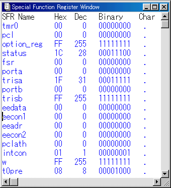
Window > Special Function Registers or 
 File Registers File Registers
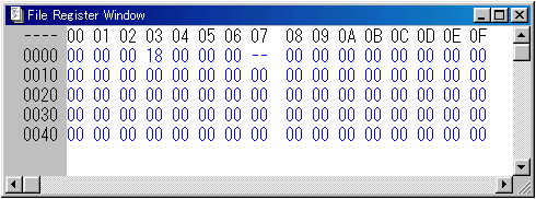
Window > File Registers or 
In the following explanation, the address of the program memory( PC counter) is used to express a place of the execution of the program.
 Debugging of initialization process Debugging of initialization process
 The reset The reset
Click the  button and it makes PIC a condition immediately after the turning on. button and it makes PIC a condition immediately after the turning on.
A dark bar is displayed on the line of PC=0000.
 The debugging by the step operation The debugging by the step operation
While clicking the  button, confirm operation. button, confirm operation.
| PC | Checkpoint |
| 0000 | : | It jumps to PC=0005. |
| 0005 | : |
Status Register of SFR is changed into 3Ch from 1Ch.
RP0 becomes '1' and the bank switches over to '1'. |
| 0006 | : | It sets FFh to W Register but because it is FFh already, there is not a change. |
| 0007 | : |
It sets FFh to TRISA Register. Only 5 bits are effective because the A port is only five.
TRISA is 1Fh already, there is not a change. |
| 0008 | : |
It clears TRISB Register in 0.
All B ports are set as the output port by this. |
| 0009 | : |
It changes a bank to '0'.
Status Register of SFR is changed into 1Ch from 3Ch. |
| 000A | : | It sets FFh to W Register but because it is FFh already, there is not a change. |
| 000B | : |
It sets FFh to PORTB Register.
Because it is FFh already here, too, there is not a change. |
The debugging of initialization processing ended above.
 Debugging of switch scan and LED blink process Debugging of switch scan and LED blink process
After the initialization processing ends, the program counter becomes 000Ch. The content of PORTA Register which made input mode is All'0'. It debugs all switches as the 'ON' condition.
 The debugging by the step operation The debugging by the step operation
While clicking the  button, confirm operation. button, confirm operation.
| PC | Checkpoint |
| 000C | : | Because the content of PORTA is all '0', the BTFSS instruction executes the instruction of the following address ( 000Dh ). |
| 000D | : |
It jumps to ( 0017h ) at the head of the PATTREN 0 LED blink processing subroutine.
Because it is a jump to the subroutine, a return address is stored in STACK.
Confirm the contents of STACK.
The STACK window can be displayed in Window > Stack.

Address ( 000Eh ) after the address to have called a subroutine as the return address is stored in STACK.
|

Since then, it is the debugging of LED blink process. |
| 0017 | : | It sets FEh to W Register. Confirm that w of SFR is changed into FEh from FFh. |
| 0018 | : | It sets FEh to PORTB Register. Confirm that portb of SFR is changed into FEh from FFh. |
| 0019 | : |
It jumps to the timer subroutine to secure the lighting-up time of the LED.
In case of Pattren 0, it jumps to address ( 00C0h ) at the head of the 100-millisecond timer.
Confirm that 001Ah was written as the return address in STACK. |
The switch scan and the LED blink processing executes the combination of the processing by each condition.
Each blink pattern can be confirmed in the way by the breakpoint. However, because it takes a lot of time, the confirmation of each pattern had better go in actual PIC.
 Debugging of timer process Debugging of timer process
The basic timer processing of the timer processing is a 1-millisecond timer.
When using a 10-MHz oscillator, it becomes 1 millisecond when executing 2500-cycle instructions.
 The change of the program counter The change of the program counter
There is a way of having a program counter at the head of the 1-millisecond timer using the breakpoint.
However, here, it does in the way of changing a program counter into direct.
The dialog of the program counter change is displayed in Debug > Run > Change Program Counter... or  . .

Input the program counter value to want to change into the item of the PC in the hexadecimal. When clicking the Change button, the program counter changes.
This time, it enters 00B5. Confirm that the dark bar of the program counter is moved to 00B5.
 The debugging by the step operation The debugging by the step operation
While clicking the  button, confirm operation. button, confirm operation.
| PC | Checkpoint |
| 00B5 | : |
It sets ( 2 ) with the 1st loop count value to W Register.
Confirm that w of SFR becomes 2. |
| 00B6 | : |
It stores a counter value in the RAM register file. The address is Dh of the RAM register.
Confirm that Dh becomes '2'. |
| 00B7 | : |
It sets ( 249 ) with the 2nd loop count value to W Register.
Confirm that w of SFR becomes F9h. |
| 00B8 | : |
It stores a counter value in the RAM register file. The address is Ch of the RAM register.
Confirm that Ch becomes 'F9h'. |
00B9
00BA | : |
It is the dummy step to make the processing time.
There is no processing but an instruction cycle is used. |
| 00BB | : |
It count-downs a loop counter and does the judgement whether or not the counter became '0'.
The value of 0Ch of the RAM file register changes to F8h form F9h.
Because the subtracted result is not '0', the program counter moves to the following address (00BC). |
| 00BC | : | It jumps to 00B9 to process a loop. |
After that, the processing of a counter subtraction is done.
Because there is not a meaning even if it confirms any more by the step operation, it confirms by the breakpoint.
 Debugging by the breakpoint Debugging by the breakpoint
The breakpoint can be set by following procedure.
| (1) | Click the step to want to make stop processing and it moves a cursor. This time, it is 00BFh. |
(2)
 |
Click the right button of the mouse.

Choose Break Point(s) in the displayed menu and click the left button of the mouse.
The line which a breakpoint was set to changes to the red. |
A breakpoint was set by above operation.
Next, click the  button. It is possible to make this operation to be Debug > Run > Run. button. It is possible to make this operation to be Debug > Run > Run.
After a little time passes, the bar of the program counter stops in 00BFh.
While MPLAB is executing a program(Simulation), the status bar which is under the screen becomes yellow.
It is very slow that MPLAB works a simulation compared with the operation of actual PIC. The simulation of 1-millisecond processing in PIC takes for about 1 second.(About 1000 times) I think that it depends on the personal computer to use, too.
In case of the 1-millisecond timer, I think that it stops within several seconds. When not stopping after tens of minutes, too, it checks the program to be debugging or the setting of a breakpoint.
 The confirmation of the operating time by the stopwatch function The confirmation of the operating time by the stopwatch function
There is the stopwatch function in MPLAB. This is the function to display a processing time in PIC by counting the execute cycles. So, the processor frequency of PIC to use actually must be set right.
The setting of a processor frequency in MPLAB(Ver5.00) can be set in CLOCK in the dialog which is displayed in Options > Development Mode... .
Also, the window of the stopwatch can be displayed in Window > Stopwatch .
The result which measured the time of the 1-millisecond timer is shown below.
| (1) |
Start from the step to be calling the 1 millisecond timer subroutine in the 100-millisecond timer.
Set a program counter to 00C2. |
| (2) | Set a breakpoint to 00C3. |
| (3) |
Display a stopwatch window.
When the number of the cycles is not 0 when displaying, click the Zero button and make a display 0. |
| (4) | Click the  button. button. |
(5)
 |
A result is displayed as follows.

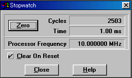
It shows to have been 2503 cycles taken by stopping after starting. It becomes 1.00 milliseconds when converting at the processor frequency of 10 MHz.
In case of the way this time, subroutine call instruction (CALL) with the 100-millisecond timer is contained in the execute step. So, 2501 cycles taken a 1-millisecond timer. |
In case of the timer by the software, because it is making waiting time with processing step, it isn't correct. The timer in 1 second is using a 1-millisecond timer 1000 times. 1-cycle error with the 1-millimeter timer becomes 1000-cycle error with the timer in 1 second. Moreover, the processing to call a subroutine, the setting processing of a loop counter and so on, too, are added. If wanting correct time, it had better use a hard timer.
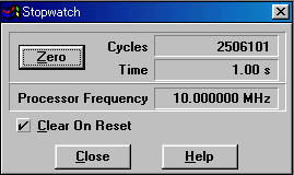
The measurement result of the timer in 1 second is shown below. By this measurement, my personal computer needed for 18 minutes.
The 6101-cycle error is 2.44 milliseconds when converting to the time.
There is not a problem in the LED blink control at all.
Depending on the circuit to use, the influence may come out.
 |


