Pulse width of synchronizing signal Pulse width of synchronizing signal
 The starting point of TRIAC control is the polarity reversals ( 0V ) of alternating voltage. A photo coupler is used for detecting polarity reversals. Alternating voltage is applied to LED of a photo coupler, and a synchronization pulse is generated when LED puts out the light by 0V. I measured the pulse width of an actual circuit. A measurement circuit is shown in the left figure. PIC is not mounted yet. If PIC is mounted, pulse width will change. The starting point of TRIAC control is the polarity reversals ( 0V ) of alternating voltage. A photo coupler is used for detecting polarity reversals. Alternating voltage is applied to LED of a photo coupler, and a synchronization pulse is generated when LED puts out the light by 0V. I measured the pulse width of an actual circuit. A measurement circuit is shown in the left figure. PIC is not mounted yet. If PIC is mounted, pulse width will change.
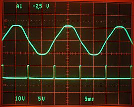
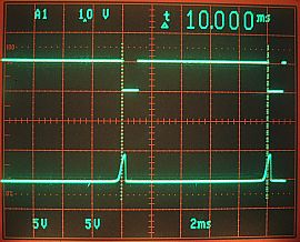
The pulse has come out in the position of the polarity reversals of alternating voltage.
The range of the alternating voltage( upper ) is 10V/div and the synchronization pulse( lower ) is 5V/div. The sweep is 5ms/div. |
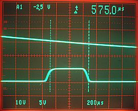
The width of a synchronization pulse is about 580 microseconds.
There are some jitters in rising edge and falling edge. However, it doesn't influence circuit operation. |
Detection of synchronization pulse
The above-mentioned synchronization pulse is recognized by interruption of RB0 port. This operation cannot be checked by the simulator of MPLAB. Then, I made the software for the interruption operation check of RB0 port. The number of times of interruption of RB0 port is counted, and RA0 port is made ON or OFF every 100 times. You can check the operation by connecting LED to R1. Since a synchronization pulse occurs at intervals of 10 milliseconds in the case of 50Hz, LED blinks for every second. Since it is 8.3 milliseconds intervals in the case of 60Hz, it becomes early a little. A check here is not measuring time correctly. The purpose of this check is confirmation of interruption operation of RB0 port. So, it's OK. if it is blinking in about 1 second. When interruption operation is not normal, it doesn't light up at all or it continues to light up.
Switch reading and TRIAC trigger signal
By the simulator of MPLAB, the check of reading operation of a switch is impossible. Then, I made the following test program and checked the reading operation of switches, and the trigger signal of TRIAC control.
The switch mode (swx_mode) read by switch reading processing of TMR1 is set as TRIAC control data (triacx). In the case of a switch 1, the data of sw1_mode is copied to triac1. Thereby, the state of a switch can be checked by the signal of Port A.
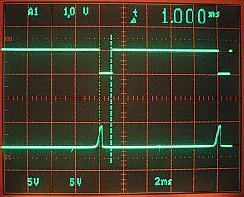
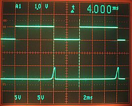
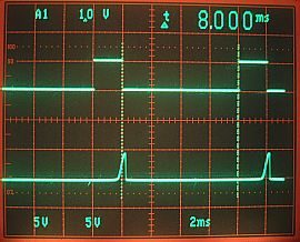
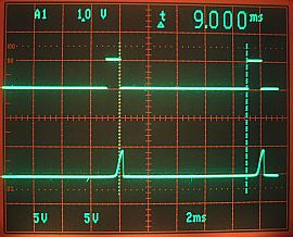
The signals measured are the synchronization pulse of RB0 (it's the lower side on an oscilloscope screen), and an output signal of RA0 (it's the upper side on an oscilloscope screen).
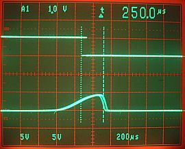
First, I checked the synchronization pulse. The value measured without connecting PIC is differed from. Pulse width is below half. This is considered because the pull-up resistor value of PIC is smaller than 3k-ohm. Trouble is not on operation of this equipment. |
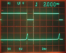
This is the screen which measured the interval of a synchronization pulse. Since the frequency of alternating voltage is 50Hz, the intervals of a synchronization pulse are 10 milliseconds. |
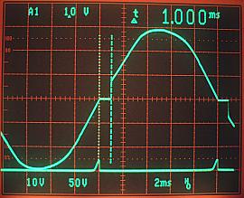
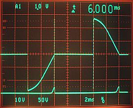
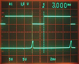
This is a screen when setting a BCD switch to 0 or 1. You can find that the control signal of the TRIAC becomes ON 1 millisecond later after detecting a synchronization pulse.
With this equipment, even when the data for TRIAC control is 0, it borrows in 1 millisecond until a control signal comes out. |
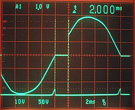
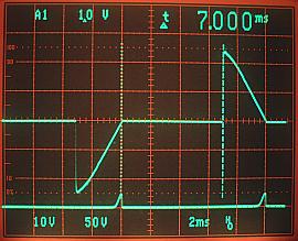
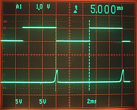
BCD switch is set to 2. |
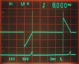
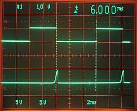
BCD switch is set to 3. |
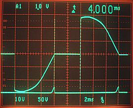
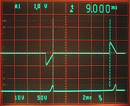
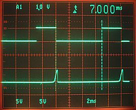
BCD switch is set to 4. |
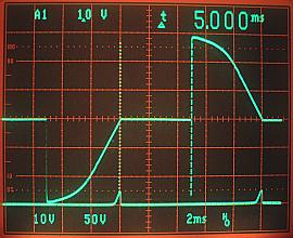
BCD switch is set to 5. |
BCD switch is set to 6. |
BCD switch is set to 7. |
BCD switch is set to 8. |
BCD switch is set to 9. |
|
| It has checked that reading processing of switches and control signal processing of TRIACs were performed normally. |
Controlled alternating voltage
I checked the drive circuit control signal outputted from a control circuit at the previous section. In this section, I connect a control circuit and a drive circuit and observe the wave form of the alternating voltage applied to the lamp.
The software to be used is the same as a previous section. The electric bulb of 60W is used for load. One of the two of a commercial power supply line may be grounded. Therefore, I used the isolation transformer, in order to prevent the short circuit of a measurement circuit. One of the two of the isolation transformer is connected to grounding of a control circuit. This is for carrying out grounding of an oscilloscope in common. When grounding is connected, there may be those who think that current flows into both two circuits. Current flows, when plus and minus are connected with. Therefore, even if only the line of one is connected, current doesn't flow.
|