Operation confirmation of the receiver circuit Operation confirmation of the receiver circuit
At first, I was doing to the conception to load a receiver circuit on the display processing circuit. However, I canceled the conception for the following reason. Then, I decided to accommodate the display circuit of the time and the receiver circuit in the different cases and connect them with the cable.
 Reception fault by the foreign noise Reception fault by the foreign noise
Time information is transmitted by the radio wave of 40KHz. The place in which I live is about 200km(124mi) away from the transmitting station. Therefore, it becomes difficult to receive normally when there is a noise outside.
If a receiver circuit is put on a display processing circuit, the oscillator of a display processing circuit may block a radio wave, and it may be unable to receive. This phenomenon has improved by inserting the board of aluminum grounded between the display processing circuit and the receiving circuit. A switching regulator turns into a noise generation source. I had placed the circuit near the switching regulator for the examination. Therefore, the radio wave was normally unreceivable.
An radio wave cannot be seen by the eye. If there is no special measuring instrument, it is very difficult to trace the cause by which a receiver does not operate normally.
Direction of an antenna
 If a bar antenna is arranged at the direction and right angle at which a radio wave arrives, a radio wave is receivable good. It may be unreceivable if it is made parallel with the arrival directions of a radio wave. Although based also on the strength of the coming radio wave, this arrangement influences a receiving situation greatly. When a receiver circuit is included in the clock itself, if direction of an antenna is adjusted, it will be assumed that it is hard coming to see the display section of a clock. The coil of the antenna for the exteriors is wound around the edge of a bar antenna, and using an external antenna is also considered. I removed the power circuit and the RS232C circuit, in order to carry out the stack of a display processing circuit and the receiving circuit. There was no need. If a bar antenna is arranged at the direction and right angle at which a radio wave arrives, a radio wave is receivable good. It may be unreceivable if it is made parallel with the arrival directions of a radio wave. Although based also on the strength of the coming radio wave, this arrangement influences a receiving situation greatly. When a receiver circuit is included in the clock itself, if direction of an antenna is adjusted, it will be assumed that it is hard coming to see the display section of a clock. The coil of the antenna for the exteriors is wound around the edge of a bar antenna, and using an external antenna is also considered. I removed the power circuit and the RS232C circuit, in order to carry out the stack of a display processing circuit and the receiving circuit. There was no need.
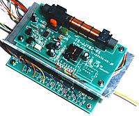
 The receiver circuit was put into the case different from the main part of a clock, and it has connected with the cable this time. Thereby, the position of a receiving antenna can be decided regardless of the position which places a clock. The receiver circuit was put into the case different from the main part of a clock, and it has connected with the cable this time. Thereby, the position of a receiving antenna can be decided regardless of the position which places a clock.
Although the check of a receiving situation can be checked by a LCD display and Rx LED, it takes time somewhat. A receiving situation can be checked also by TCO LED. When time information can be received, TCO LED blinks at intervals of 1 second. The time which TCO LED has turned on changes somewhat with information sent But finally, it is necessary to check the time displayed on LCD.
A left figure is the time code of the information sent through radio. A certain signal is sent for every second. In order to receive all information, the time for 1 minute or more is required.
|