 |  |
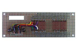
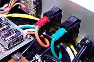
| This is the picture which connected the cathode of the 7 segment LED in parallel. | This is the picture of the anode and the control status display LED wiring. |
|
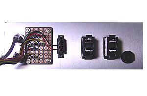 |  |
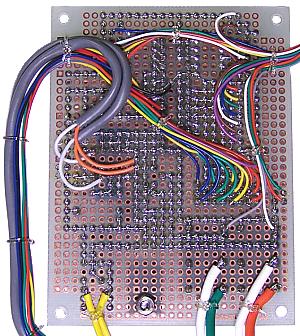
| This is the picture of wiring of the back panel. Wiring of temperature sensors, BCD switches, and slide switch are performed. Cable connection of AC power supply is performed after wiring to a printed circuit board finishes. | The shielded cable is used for wiring of temperature sensors. The mini jack for audio stereos is used for the sensor connector. Since it is 3P, it is necessary to decide the position of wiring. I used the outside as ground,, the middle as the sensor output and the center as the power supply. |
|
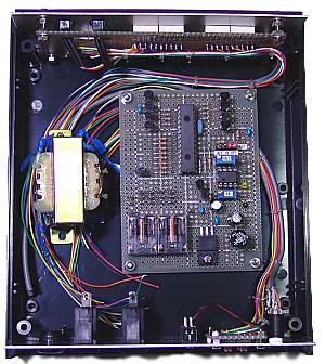 |  |
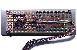
| Before wiring to a printed circuit board, the position of main parts is checked. | This is the picture which the wiring to a printed circuit board completed. |
|
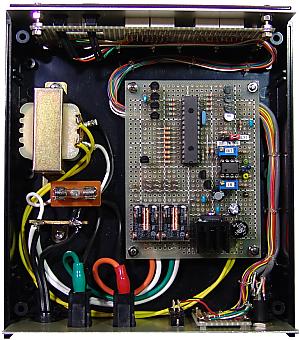
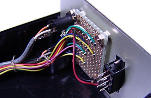
This is the picture which all wiring completed.
Power supply wiring is wired to the transformer circuit and the output circuit via the terminal. Wiring of an electronic circuit and wiring of AC power supply are detached as much as possible. |
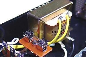
This is wiring of the power supply.

This is wiring of output connectors. |
|
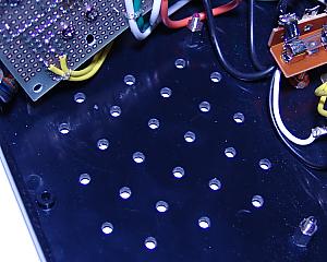 | 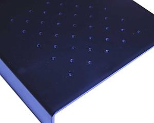 |
| The holes for heat dissipation have opened in the bottom of a case. | There are holes for heat dissipation also in the lid of a case. |