Troubleshooting of Room temperature controller
|
Some troubles occurred in the process of this project. I put these for reference.
Cause : Because the bank of a memory was not set up by interruption processing. Measure : The bank was set as 0 at the beginning of interruption processing. The following composition is adopted in this processing. The display of LED and reading of SW are base level processings (processing which is not interruption). Reading of temperature sensor is interruption processing of timer 0. Control of external circuit is interruption processing of timer 1. In base level processing, PORTB is set as output mode in LED processing, and set as an input mode in SW reading processing. This mode change is performed by setting change of the TRISB register on the bank 1. Since base processing is interrupted, W register and STATUS register saved at the beginning of interruption processing. And when interruption processing is completed, those registers are returned to the original contents. This phenomenon will occur, if interruption is carried out while changing bank 1 on a base level and performing processing of TRISB register. Since the bank had changed to 1, the memory in interruption processing was not able to be operated normally. There is a method of forbidding interruption by processing of a base level as other solutions. Before memory processing competition arises, the GIE bit of an INTCON register is set to 0, and interruption is forbidden and setting GIE to 1 at the end of memory processing and enabling interruption of it. tempcont.asm
Cause : Because the temperature sensor oscillated. Measure : Multiple connection of the capacitor was carried out to the output of a sensor. 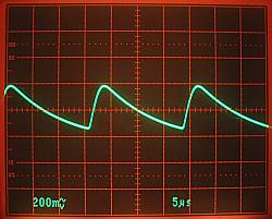 With this equipment, in order to measure indoor temperature and outdoor temperature, two temperature sensors are used. The phenomenon occurred by one of them. A temperature display changes scatteringly and is not stabilized. When two sensors were replaced, the phenomenon moved. It is the peculiar phenomenon of one of the two's sensor. The phenomenon was not repaired although exchanged for a new sensor. The oscillation phenomenon was checked with the oscilloscope. The length of a cable seems to be related. Although how to change a cable was considered, I decided to put a capacitor into the output of a sensor. The oscillation stopped by putting in a 0.1-micro F capacitor. Although it does not change a lot like when oscillating, the temperature display is changing in several °C. This was the same also as two sensors. When capacity of a capacitor was set to 2.2 micro F, very small change of a temperature display was lost. Change of a temperature display is also normal. The resistor for capacitor electric discharge is not attached. It discharges by the sensor and an operational amplifier. Cause : Because reading of a BCD switch is unstable. Measure : When the same value was able to be read continuously 3 times, it was presupposed that it is effective. The conditions which drive an external circuit are the following conditions. In case of UP mode, external circuit is operated, when room temperature is higher than preset temperature and higher than outdoor temperature. But even when room temperature was lower than preset temperature, the phenomenon in which an external circuit operated occurred. The fault of software is not found. Then, the trap was devised to comparison processing of room temperature and preset temperature. When detecting that room temperature was high in the situation where preset temperature is higher than room temperature, it was made for a control circuit 2 to operate. When several minutes had passed, the circuit 2 operated. This time is not fixed. There is a case of several minutes, and there is a case of tens of minutes. Next, reading processing of a BCD switch was checked. The read value was saved and it compared with the next reading. Thereby, carrying out a reading error was checked. A cause is not certain. Even when reading waiting time is doubled( 200 microseconds ) , a phenomenon does not change. Investigation of the primary cause seems to be difficult. Then, I judged that it was infallible, when the same value could be read continuously three times. The time which reading takes 3 times is an about 25 milliseconds. On the other hand, temperature comparison processing is the cycles of 2 seconds. Although read 3 times, there is no problem. Even if reading goes wrong, since the value read before that can be used, a problem does not have this, either. Moreover, since the change frequency of preset temperature is low, it does not become a trouble. Although it was not fundamental management, since it was substantially satisfactory, I decided to adopt this method. Henceforth, malfunction by this phenomenon has not been carried out. tempcont.asm
Cause : Because input voltage is high, a regulator generates heat also a little current. Measure : The output voltage of the transformer was lowered and a heat sink was attached.  This phenomenon is natural. But it is easy to overlook. Reference "Circuit explanation for +5V Switching regulator" This phenomenon is natural. But it is easy to overlook. Reference "Circuit explanation for +5V Switching regulator"The transformer of AC12V was used at first. In this case, regulator input voltage when two relays operate was 14.15V, and current was 0.15A. Therefore, the electric power consumed by the regulator is ( 14.15V - 5.00V ) x 0.15A = 1.37W. When the output of the transformer was changed into AC10V, regulator input voltage when two relays operate was 11.10V. Therefore, the electric power consumed by the regulator is ( 11.10V - 5.00V ) x 0.15A = 0.92W. Although it is about 0.5W difference, generation of heat is suppressed. The difference of the input voltage and output voltage of a regulator is 3V grade necessity. Therefore, it is necessary to use the transformer beyond AC8V at the lowest. Although the transformer output was incidentally set to AC7V, when two relays operated, equipment did not work normally. Since remarkable heat comes also out of the power consumption of 0.92W from the regulator, it is necessary to attach a heat sink. |