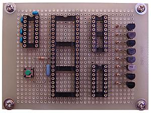
This is the board which receives time information from the CPU unit with a RS232C interface, and controls LEDs.
The driver of RS232C is mounted on the upper left socket and PIC16F877A is mounted on the central big socket. The right side sockets and transistors are used to control the day-of-the-week display. PIC16F628 is mounted on the upper socket and
74HC138 is mounted on the bottom.
A lower left green button is an LED display test switch. | This is the photograph of the wiring side. |