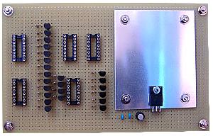
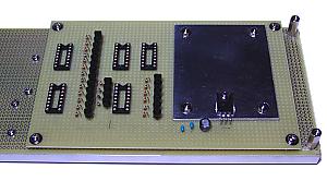
This board drives the 7 segment LEDs with the signal of the display control unit. The transistor arrays (TD62003) are mounted on in the sockets of the three upper left. The decoders for LED scan (74HC138) are mounted on two lower sockets
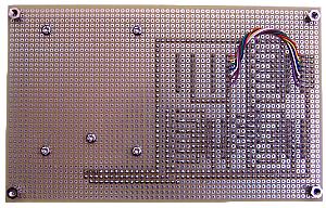
Right side is 7805 and the heat sink which make +5V from a power supply. A heat sink is an aluminium board of 2mm thickness. It is satisfactory even if a heat sink is somewhat small. I made the space of the printed circuit board suit. | This is the photograph of the wiring side. Many lines are wired to this board at the time of completion. |