 |  |
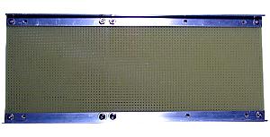
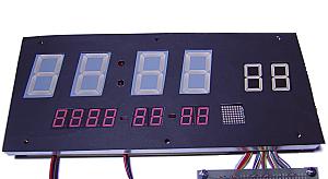
| Two printed circuit boards are used for the panel. They are connected with the aluminum bar of L form, in order to maintain intensity. | This is the photograph which carried out temporary arrangement of the LEDs. They are Hour, Minute, and Second from the upper left, and Year, Month, Day and Week from lower left.. |
|
 |  |
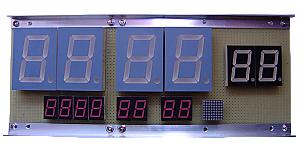
| The height of LED changes with the size. The LED for Hour and Minute is the highest one. So other LEDs are mounted on another PCB to adjust the height. | This photograph shows the display panel by which all LEDs are mounted. |
|
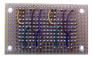 | 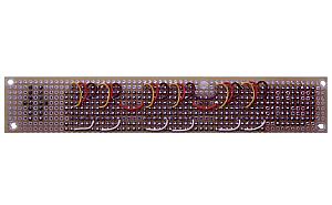 |
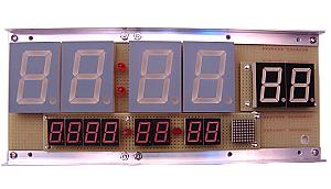
| This is the wiring side of the 7 segment LED board which displays a second. In order to wire the cathode of each LED, there is wiring of seven. | This is the board of LED which displays Year, Mounth, Day, and Week. A left end is the LED matrix for a day of the week. |
|
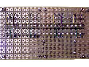 |  |
| This is the wiring side of the display panel. Seven common lines are used also here. | The cover of a purple acrylics board is attached in the display panel. The light of LED becomes vivid with a purple acrylics board. The cover consists of the transparent acrylics board of 0.5mm thickness to the bottom, the mask of black paper on it, and the purple acrylics board of 2mm thickness to the top. The bottom transparent acrylics board is a support of the mask. |
|
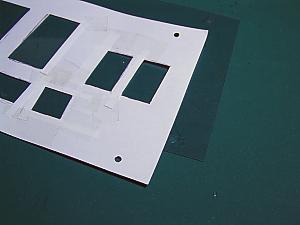 | 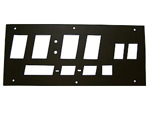 |
| The hole of the mask is only the luminescence portion of LED. In order to make the position of holes exact, the white paper as a temporary mask was used. Since white paper can have somewhat seen back, it is easy to check the position. Compensation of the size of a hole can also be performed. A transparent acrylics board appears black under white paper with a photograph. | The temporary mask in white paper is applied to black paper, and holes are made correctly. The holes of four corners are the holes which fixe the cover to spacer. The holes of the central upper and lower sides are holes which fixe composition articles. Thereby, even if it removes a cover, the position of a mask does not shift. |
|
 |  |
| This is the photograph which put the mask on the display panel. This mask is not indispensable. This is the bandage which carries out beautiful of the display panel. | This is the photograph which attached the cover in the display panel. The segment of LED is known with the photograph. Usually, the segment which is not emitting light is seldom visible. |
|
|