 |  |
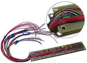
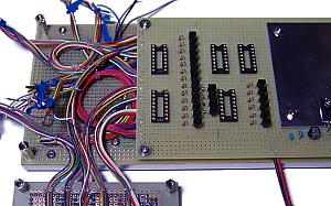
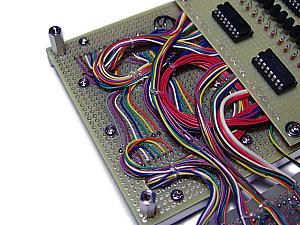
This is the photograph of wired panel of Year, Month, Day and Week. The wiring is tied for every kind. For example, a wire with different color is used for each cathode of the LED matrix and is tied by one.
Moreover, since the distance between printed circuit boards is narrow, it is fixing with the string of vinyl so that the bunch of wiring may become even. | This is wiring of a second display panel. The length of each wiring is made somewhat long slightly. |
|
 |  |
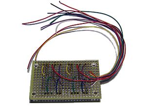
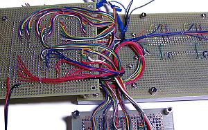
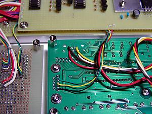
| This is wiring of the display panel. Left-hand side wiring is the wiring from the panel of Year, Month, Day, Week and Second. Since the LED of Hour and Minute is common cathode type LED, the blue wire is used for wiring of cathode. | This is wiring of the LED drive unit. The drive unit is attached in the back of the display panel, and the interval is 5mm. Therefore, the wiring is flattened as much as possible. The common terminal of the 7 segment LED is not connected with this photograph. The wiring from the display panel is connected later. |
|
 |  |
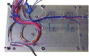
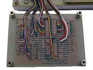
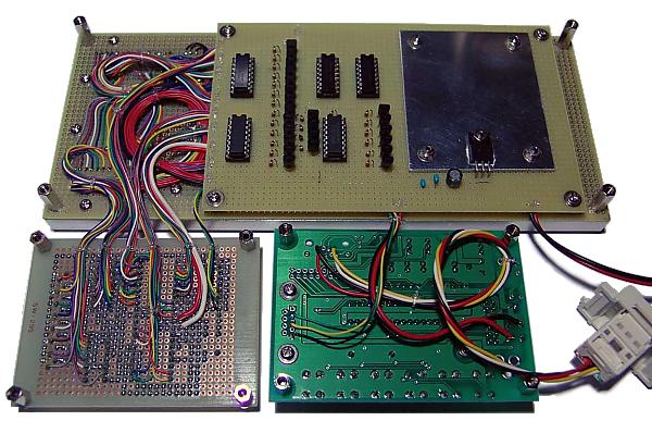
| This is the photograph which wiring completed mostly. Wiring of the brilliance control resistors has not been completed. Wiring with a display panel and each unit is made somewhat long slightly. | This is the photograph which removed the LED drive unit from the display panel. Since wiring is lengthened slightly, the wiring side can be checked comfortably. |
|
 | 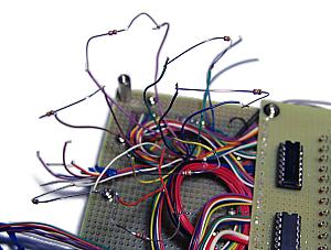 |
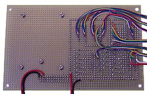
| This is the photograph of display control unit wiring. Wiring is fixed to the end of the printed circuit board in vinyl cord so that power may not be applied to the soldering portion of wiring. |
This is a photograph when carrying out brilliance control of LED. The brilliance control resistor is temporarily connected to each segment. The resistance is changed and the brightness of LED is adjusted. Since there are seven resistors, changing-value work is serious.
I used "jjym_test1" program, when carrying out brilliance control. The numerical value displayed on LED can be changed by this program, or all segments can be turned on with a LAMP TEST switch. |
|
 |  |
| This is the photograph which wiring of the resistors for LED brilliance control completed. Wiring is arranged by the vinyl string. | Display control unit(Left) and CPU unit(Roght) are connected by the wiring for RS232C. They are transmission, reception, and grounding. The transmitting line of the CPU unit is connected to the receiving terminal of the display control unit. Moreover, the transmitting line of the display control unit is connected to the receiving terminal of the CPU unit. |
|
 |
| This is the photograph which all wiring completed. A lower right connector is RJ-45 connector connected with a receiver unit by a LAN cable. |
|
|