Resistors
|
The resistor's function is to reduce the flow of electric current. This symbol  is used to indicate a resistor in a circuit diagram, known as a schematic. is used to indicate a resistor in a circuit diagram, known as a schematic.Resistance value is designated in units called the "Ohm." A 1000 Ohm resistor is typically shown as 1K-Ohm ( kilo Ohm ), and 1000 K-Ohms is written as 1M-Ohm ( megohm ). There are two classes of resistors; fixed resistors and the variable resistors. They are also classified according to the material from which they are made. The typical resistor is made of either carbon film or metal film. There are other types as well, but these are the most common. The resistance value of the resistor is not the only thing to consider when selecting a resistor for use in a circuit. The "tolerance" and the electric power ratings of the resistor are also important. The tolerance of a resistor denotes how close it is to the actual rated resistence value. For example, a ±5% tolerance would indicate a resistor that is within ±5% of the specified resistance value. The power rating indicates how much power the resistor can safely tolerate. Just like you wouldn't use a 6 volt flashlight lamp to replace a burned out light in your house, you wouldn't use a 1/8 watt resistor when you should be using a 1/2 watt resistor. The maximum rated power of the resistor is specified in Watts. Power is calculated using the square of the current ( I2 ) x the resistance value ( R ) of the resistor. If the maximum rating of the resistor is exceeded, it will become extremely hot, and even burn. Resistors in electronic circuits are typicaly rated 1/8W, 1/4W, and 1/2W. 1/8W is almost always used in signal circuit applications. When powering a light emitting diode, a comparatively large current flows through the resistor, so you need to consider the power rating of the resistor you choose. Rating electric power
However, if you try to drop the voltage from 12V to 5V using only a resistor, then you need to calculate the power rating of the resistor as well as the resistance value. At this time, the current consumed by the 5V circuit needs to be known. Here are a few ways to find out how much current the circuit demands. Assume the current consumed is 100 mA (milliamps) in the following example. 7V must be dropped with the resistor. The resistance value of the resistor becomes 7V / 0.1A = 70(ohm). The consumption of electric power for this resistor becomes 0.1A x 0.1A x 70 ohm = 0.7W. Generally, it's safe to choose a resistor which has a power rating of about twice the power consumption needed.
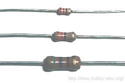
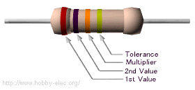
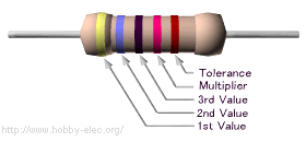
For example, in the case of E3, The values [1], [2.2], [4.7] and [10] are used. They divide 10 into three, like a logarithm. In the case of E6 : [1], [1.5], [2.2], [3.3], [4.7], [6.8], [10]. In the case of E12 : [1], [1.2], [1.5], [1.8], [2.2], [2.7], [3.3], [3.9], [4.7], [5.6], [6.8], [8.2], [10]. It is because of this that the resistance value is seen at a glance to be a discrete value. The resistance value is displayed using the color code( the colored bars/the colored stripes ), because the average resistor is too small to have the value printed on it with numbers. You had better learn the color code, because almost all resistors of 1/2W or less use the color code to display the resistance value.
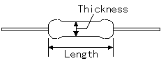
Carbon film resistors have a disadvantage; they tend to be electrically noisy. Metal film resistors are recommended for use in analog circuits. However, I have never experienced any problems with this noise. The physical size of the different resistors are as follows.
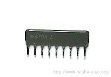 This resistor is called a Single-In-Line(SIL) resistor network. It is made with many resistors of the same value, all in one package. One side of each resistor is connected with one side of all the other resistors inside. One example of its use would be to control the current in a circuit powering many light emitting diodes (LEDs). In the photograph on the left, 8 resistors are housed in the package. Each of the leads on the package is one resistor. The ninth lead on the left side is the common lead. The face value of the resistance is printed. ( It depends on the supplier. ) Some resistor networks have a "4S" printed on the top of the resistor network. The 4S indicates that the package contains 4 independent resistors that are not wired together inside. The housing has eight leads instead of nine. The internal wiring of these typical resistor networks has been illustrated below. The size (black part) of the resistor network which I have is as follows: For the type with 9 leads, the thickness is 1.8 mm, the height 5mm, and the width 23 mm. For the types with 8 component leads, the thickness is 1.8 mm, the height 5 mm, and the width 20 mm. 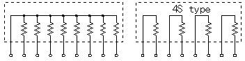
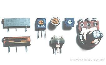 In the photograph to the left, the variable resistor typically used for volume controls can be seen on the far right. Its value is very easy to adjust. The four resistors at the center of the photograph are the semi-fixed type. These ones are mounted on the printed circuit board. The two resistors on the left are the trimmer potentiometers. This symbol 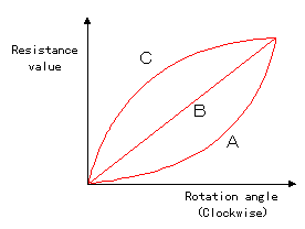 There are three ways in which a variable resistor's value can change according to the rotation angle of its axis. When type "A" rotates clockwise, at first, the resistance value changes slowly and then in the second half of its axis, it changes very quickly. The "A" type variable resistor is typically used for the volume control of a radio, for example. It is well suited to adjust a low sound subtly. It suits the characteristics of the ear. The ear hears low sound changes well, but isn't as sensitive to small changes in loud sounds. A larger change is needed as the volume is increased. These "A" type variable resistors are sometimes called "audio taper" potentiometers. As for type "B", the rotation of the axis and the change of the resistance value are directly related. The rate of change is the same, or linear, throughout the sweep of the axis. This type suits a resistance value adjustment in a circuit, a balance circuit and so on. They are sometimes called "linear taper" potentiometers. Type "C" changes exactly the opposite way to type "A". In the early stages of the rotation of the axis, the resistance value changes rapidly, and in the second half, the change occurs more slowly. This type isn't too much used. It is a special use. As for the variable resistor, most are type "A" or type "B".
There are many types of these devices. They vary according to light sensitivity, size, resistance value etc. 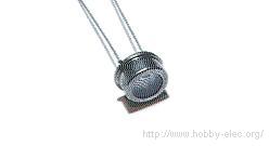 This device is using for the head lamp illumination confirmation device of the car, for example.
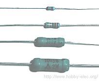
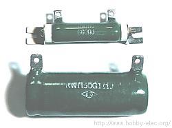
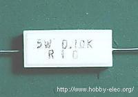
A wirewound resistor is made of metal resistance wire, and because of this, they can be manufactured to precise values. Also, high-wattage resistors can be made by using a thick wire material. Wirewound resistors cannot be used for high-frequency circuits. Coils are used in high frequency circuits. Since a wirewound resistor is a wire wrapped around an insulator, it is also a coil, in a manner of speaking. Using one could change the behavior of the circuit. Still another type of resistor is the Ceramic resistor. These are wirewound resistors in a ceramic case, strengthened with a special cement. They have very high power ratings, from 1 or 2 watts to dozens of watts. These resistors can become extremely hot when used for high power applications, and this must be taken into account when designing the circuit. These devices can easily get hot enough to burn you if you touch one.
 The resistance value of the thermistor changes according to temperature. This part is used as a temperature sensor.
|