Like a standard USB serial adapter, the RLC-3 is connected to your PC via the standard USB connector, and driver software is installed to make it appear as a new serial port; accessible by any PC software which can talk to a com# port. Com port drivers are automatically installed with Windows XP / Vista (Microsoft WHQL certified) and are available for Macintosh OSX, Linux, WinCE, and Windows 2k / 2k3 / 7.
TTL compatible input / output: Unlike a standard USB serial adapter, the output lines of the RLC-3 are already converted from the RS232 +/- 12 volt level signals to TTL compatible signal levels, making it ideal for communications with microcontrollers like those embedded in ham radios, monitors, and other devices or for your own projects where a PC must "talk" to a microcontroller like the BASIC STAMP, PIC, SX, etc...
Any format: Data formats of 5, 6, 7 and 8 data bits* with 1, 1.5* or 2 stop bits and odd, even, mark, space, or no parity are supported. *at 1M baud, only 7 and 8 data bits are supported *only 5 bit data supported with 1.5 stop bits
Any speed: Baud rate from 300 to 1M (including 300 / 600 / 1200 / 2400 / 4800 / 9600 / 14,400 / 19,200 / 28,800 / 38,400 / 57,600 / 115,200 / 576,000 / 921,600) with a 576 byte receive buffer and a 640 byte transmit buffer promote fast and smooth data transfer. USB 2.0 compliance provides full speed data transfer on the USB side.
Handshaking: Support for X-On/X-OFF. (RTS / CTS pins not accessible)
No power needed: The unit is self powered from the USB port, and can actually supply a small amount of current for a target circuit (500mA at 5V or 26mA at 3.3V).

Also:
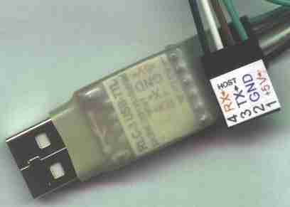
The pin order on the TTL connector is easy to change. Just slightly pry up the little plastic locking tab, and first push in, then pull out the connector by the wire.
As noted in the table below, plugging things in backwards such that the +5 supply is grounded or so that a data pin is receiving a negative voltage can stress this unit past the point of damage. Please be certain of the signals on the pins of the device you are connected before you plug it in. We recommend a few quick measurements with a multi-meter (commonly available for about the price of the RLC3) with the meters ground lead on what you believe is your devices ground pin, and the meter set to measure low voltages. Then the TX pin of your device should read either 0 or close to +5 volts while the RX pin should "float" or change it's reading especially if you touch the pin with your finger. If you read a negative voltage at any point, then you don't have the ground pin.
Pins 5 and 6 are not supported by the cable, but are present on the device. Pin 5 exposes a Reset signal which will restart the device if pulled low for more than 15uS. Pin 6 provides 3.3 Volts at up to 26mA. Custom units with a 6 pin cable are available. RTS and CTS are not available on this unit at this time.
Parameter |
Min |
Max |
Units |
|
|---|---|---|---|---|
| Ambient temperature under bias | –55 | 125 | °C | |
| Storage Temperature | –65 | 150 | °C | |
| Voltage on any I/O Pin or RST with respect to GND | –0.3 | 5.8 | Volts | |
| Voltage on VDD with respect to GND | –0.3 | 4.2 | Volts | |
| Maximum Total current through VDD and GND | — | 500 | mA | |
| Maximum output current sunk by RST or any I/O pin | — | 100 | mA | |
| Note: Stresses above those listed here may cause permanent
damage to the device. This is a stress rating only, and functional operation of the devices at or exceeding the conditions in the operation listings of this specification is not implied. Exposure to maximum rating conditions for extended periods may affect device reliability. |
||||
Parameter |
Conditions |
Min |
Typ |
Max |
Units |
|
|---|---|---|---|---|---|---|
| Supply Voltage | 3.0 | 3.3 | 3.6 | V | ||
| Supply Current1 | Normal Operation; VREG Enabled |
— | 20 | 26 | mA | |
| Supply Current1 | Suspended: VREG Enabled |
— | 80 | 100 | ìA | |
| Supply Current - USB Pull-up2 | — | 200 | 228 | ìA | ||
| Specified Operating Temperature Range | –40 | — | +85 | °C | ||
| Notes: VDD = 3.0 to 3.6 V, –40 to +85 °C unless
otherwise specified. 1. USB Pull-up Current should be added for total supply current. 2. The USB Pull-up supply current values are calculated values based on USB specifications. |
||||||
Parameters |
Conditions |
Min |
Typ |
Max |
UNITS |
|
|---|---|---|---|---|---|---|
| Output High Voltage | IOH = –3 mA IOH = –10 ìA IOH = –10 mA |
VDD – 0.7 VDD – 0.1 — |
— — VDD – 0.8 |
— — — |
V | |
| Output Low Voltage | IOL = 8.5 mA IOL = 10 ìA IOL = 25 mA |
— — — |
— — 1.0 |
0.6 0.1 — |
V | |
| Input High Voltage | 2.0 | — | — | V | ||
| Input Low Voltage | — | — | 0.8 | V | ||
| Input Leakage Current | — | 25 | 50 | ìA | ||
| VDD = 3.0 to 3.6 V, –40 to +85 °C unless otherwise specified. | ||||||
See
Questions:
Is your ttl to USB converter based on the Prolific 2303 chip series?
I've tried several converters based on this chip and they don't reliably work with windows 7.
James Newton of MassMind replies: No. Its a Silicon Labs CP2102. Rock solid, very good with Windows 7 and all.+
| file: /Techref/io/serial/RLC3.htm, 12KB, , updated: 2020/12/3 00:44, local time: 2025/8/25 01:04,
216.73.216.7,10-2-15-75:LOG IN
|
| ©2025 These pages are served without commercial sponsorship. (No popup ads, etc...).Bandwidth abuse increases hosting cost forcing sponsorship or shutdown. This server aggressively defends against automated copying for any reason including offline viewing, duplication, etc... Please respect this requirement and DO NOT RIP THIS SITE. Questions? <A HREF="http://www.massmind.org/techref/io/serial/RLC3.htm"> RLC-3 USB to TTL level serial converter</A> |
| Did you find what you needed? |
Welcome to massmind.org! |
|
The Backwoods Guide to Computer Lingo |
.