PCB of Bike computer and test accessories.
This is the modified PCB diagram that now corresponds with the Theoretical bike and test Electrical circuit Diagram.
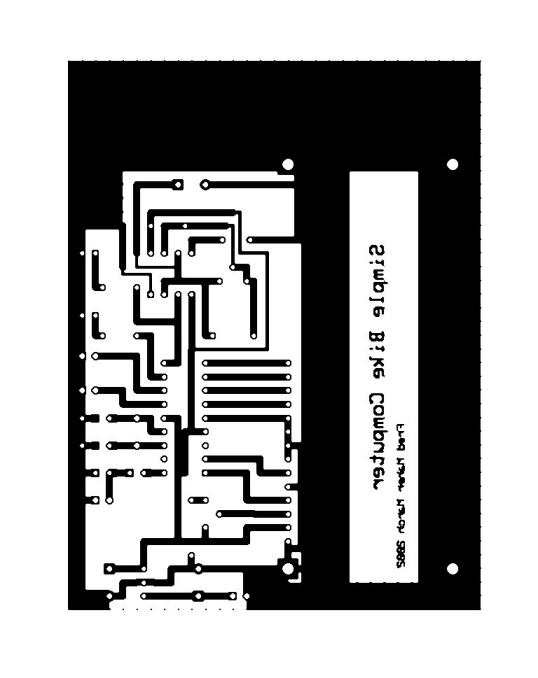
Fig.40 updated PCB for development system
The Theoretical diag. +component layout
The theoretical electrical circuit of the Bike computer circuit , the test components and a layout diagram for component placement.
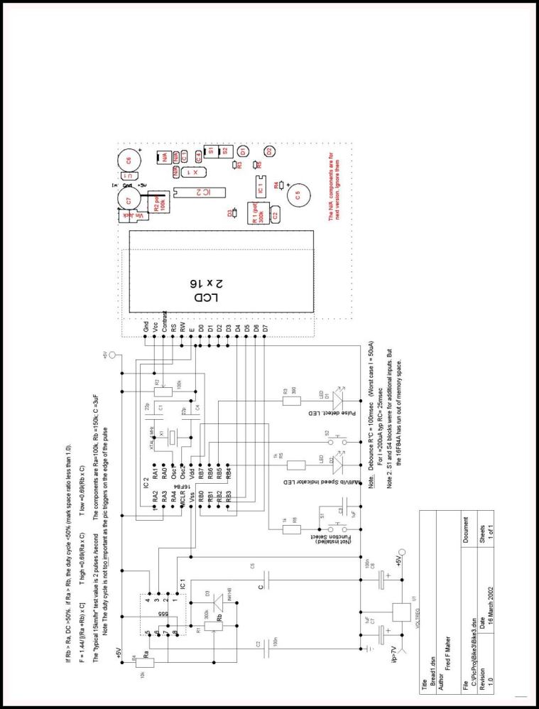
Fig.41 modified theoretical circuit for development work on simple bike computer.
Note. In the text we discovered that there
were errors in the pcb shown, which as far as I can see are now eliminated.
![]()
