 |
Note: This page is for the second version, marked ENC2 on the encoder. For the first version documentation, see ENC1
Based on the amazing
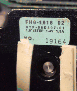
AS5134^
(76,875 RPM) or
AS5047P^
(4000 CPR), this encoder produces standard quadrature Index, A and B
phase signals just like any standard encoder. It also stores the current
position internally and that can be read out via a special digital interface.
The difference is, it uses a magnet you epoxy to the end of the motor shaft,
and it doesn't have to touch that to work. See:
How it works.


| Parameter | Min | Typ | Max | Unit |
| Supply Voltage | 4.5 | 5 | 5.5 | V |
| Current consumption | 30 | mA | ||
| Resolution (4x decoding) AS5134 AS5047P |
360 4000 |
CPR | ||
| Rated angular speed: AS5134 AS5047P |
76875 28000 |
RPM | ||
| Accuracy: Poorly aligned magnet Perfect alignment Perfect alignment, 25'C |
±1.2 ±1 ±0.8 |
degree | ||
| Data communication speed | 10 | MHz | ||
| Weight | 0.12 3.4 |
oz g |
Features:
|
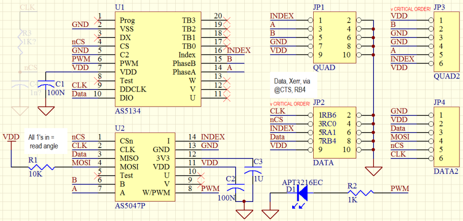
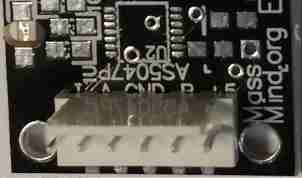
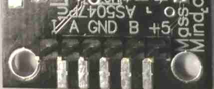
| Connector | Pin | Signal | Description |
| JP3 1x6 header |
1 | 5V | Positive supply input for the board. |
| 2 | B | Incremental encoder quadrature output. | |
| 3 | GND | Ground pin for the board. | |
| 3 | GND | ||
| 4 | A | Incremental encoder quadrature output. Channel A leads channel B by 90 degrees in clockwise rotation (top view). | |
| 6 | Index | Incremental encoder index output. | |
| JP4 1x6 header | 1 | GND | Ground pin for the board. |
| 2 | 5V | Positive supply input for the board. | |
| 3 | Data | SDA or MISO for SPI | |
| 4 | MOSI | Master Out Slave In for SPI | |
| 5 | nCS | Chip Select | |
| 6 | CLK | Clock | |
| JP1 2x5 header installed on the edge (all even pins are ground) |
1 | Index | Incremental encoder index output. |
| 3 | A | Incremental encoder quadrature output. Channel A leads channel B by 90 degrees in clockwise rotation (top view). | |
| 5 | B | Incremental encoder index output. | |
| 7 | GND | Ground pin for the board. | |
| 9 | 5V | Positive supply input for the board. (All even pins are ground) | |
| JP2 2x5 header installed on the edge (all even pins are ground) |
1 | CLK | Clock |
| 3 | nCS | Chip Select | |
| 5 | Index | Incremental encoder index output. | |
| 7 | DIO | Data | |
| 9 | 5V | Positive supply input for the board. (All even pins are ground) |
Connector Options: The board supports multiple connector types:
Single Row: If you are building this to work with the BOB PID, this is probably the best option. A Molex KK or 1x5 or 1x6 header soldered through hole can also be used. In this case, it is good to use a polarized header so that it can not be plugged in backwards and a shielded cable for long runs.
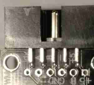 PMinMO:
A 2x5 header soldered on the edge with the PCB inserted between the pins
which are soldered along the face of the pads. Used with a 10 conductor ribbon
cable and IDC female 2x5 connector, this option has the advantage of a ground
line between each signal for very low noise and long runs.
PMinMO:
A 2x5 header soldered on the edge with the PCB inserted between the pins
which are soldered along the face of the pads. Used with a 10 conductor ribbon
cable and IDC female 2x5 connector, this option has the advantage of a ground
line between each signal for very low noise and long runs.
To install a PMinMO shrouded header, slightly bend the pins in to match the PCB thickness, then align pin one (marked with the triangle on the shroud) with the pin marked "Idx" on the edge of the PCB, The notch in the shroud should be on the top side of the PCB, where the chip is mounted. Solder a single pin, then check alignment and solder on the rest. To avoid overheating the plastic and warping the pin positions, solder one pin on the top, then the opposite pin on the bottom, alternating back and forth. It also helps to have a female IDC connector cable plugged into the header while soldering.
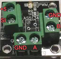 Small Terminal
Blocks. (Not included) Certain holes in the 1x6 headers have been
drilled a tiny bit larger. Those, and the two holes at the bottom of the
board, will just accomodate 2 pin 0.2" spacing terminal blocks. A slight
twisting of the blocks may be needed if they are two deep. The resulting
connections will be GND and A (bottom), GND and B (side), and +5 and SI (SI
can be ignored). The ground wires should be twised around the A / B signals
to provide maximum noise immunity.
Small Terminal
Blocks. (Not included) Certain holes in the 1x6 headers have been
drilled a tiny bit larger. Those, and the two holes at the bottom of the
board, will just accomodate 2 pin 0.2" spacing terminal blocks. A slight
twisting of the blocks may be needed if they are two deep. The resulting
connections will be GND and A (bottom), GND and B (side), and +5 and SI (SI
can be ignored). The ground wires should be twised around the A / B signals
to provide maximum noise immunity.
Bare Wires: Or you can just solder the wires directly into the holes. Some strain relief, such as threading the wires through an unused mounting hole, would be wise.
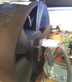
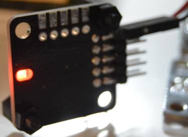
Magnet: Attach the magnet disk to the part where you need to sense angular position, e. g. front or back of the motor shaft, lead screw, ball screw, etc. The magnet should be mounted to the end of the shaft, flat against that end; a flat side of the magnet against the flat end of the shaft. For testing and alignment, the magnet will stick to any steel shaft, but vibration and shock will dislodge it. A two part epoxy is recommended for a permanent mounting. After placing the magnet, slowly turn the shaft to ensure it is centered and will not vibrate loose at higher speeds. The magnet is 0.100" thick and 0.235" diameter.
Mounting: The board must be mounted so that the chip is close (less than a half inch) to the magnet and centered over the magnet’s axis of rotation.
The board supports M3 or #4 screws. At least two screws (diagonally) should be used to hold it in position. Three screws are best. Click the picture for a detailed mounting diagram.
Turn the shaft where the magnet is attached. If the board is centered and in range of the magnet, the onboard LED will blink. Note: If the magnet is too far away, the encoder will send invalid A and B phase signals to let the controller know.
The Index, A and B phase outputs are standard quadrature encoder signals . There is also a digital interface:
On the AS5134, the easiest way to use this is in "3 wire, read only" mode:
1. Add a pull down resistor of e.g. 10K ohms to Data until you can safely
drive it low.
2. Initialize nCS and CLK as outputs set low, Data as input (again, pulled
low)
3. To start, with nCS low, bring CLK high, wait a uS, then bring CS high.
4. For each of 21 bits, wait a uS, CLK low, wait a uS, CLK high, read the
DIO pin and shift it into a long.
5. To stop, CLK low, nCS low.
The chip will see command 0 on DIO for the first 5 bits and will respond
with the angle register in the bottom 9 bits. There is some other stuff in
the middle which you can ignore. Once that is working, you can add code to
drive DIO for the first 5 bits and then listen for the next 9 and read any
register. e.g. command 4 reads the multi-turn register which has a 9 bit
count of rotations in bits 7-15. This is really nice very high speed operation.
On the AS5047P, only real SPI
communication is supported, but MOSI isn't needed to read the angle.
Arduino Code
1. Initialize nCS as an output set high and CLK as output set low, Data as
input.
2. For each of 16 bits, wait a uS, CLK high, wait a uS, CLK low, read the
DIO pin and shift it into a u_int16.
3. To stop, CLK low, nCS high.
The chip will see the command "Read Address 0x3FFF" (the ANGLECOM register)
on Data (MISO) for the first 16 bits and will respond with the angle register
in the second 16 bits; the first reading will be invalid. Once this cycle
has been completed the first time, each cycle after will continue to read
back angle data. To read or write any register, just drive MOSI. This is
less useful on the AS5047P as there is no turn register, but you can set
it for 4096 CPR.
Most often, the ENC2 will be used as input to a PID controller, such as the MassMind BOB PID.
See also:
Questions:
| file: /Techref/io/sensor/pos/enc/ENC2.htm, 13KB, , updated: 2021/12/28 10:58, local time: 2025/10/20 03:34,
216.73.216.53,10-2-207-162:LOG IN
|
| ©2025 These pages are served without commercial sponsorship. (No popup ads, etc...).Bandwidth abuse increases hosting cost forcing sponsorship or shutdown. This server aggressively defends against automated copying for any reason including offline viewing, duplication, etc... Please respect this requirement and DO NOT RIP THIS SITE. Questions? <A HREF="http://www.massmind.org/Techref/io/sensor/pos/enc/ENC2.htm"> MassMind Magnetic High Speed Non-Contact Encoder</A> |
| Did you find what you needed? |
Welcome to massmind.org! |
|
The Backwoods Guide to Computer Lingo |
.