The BOB PID is a very low cost, but quite capable, PID servo controller, which can replace stepper motors in any standard application, such as 3D printers or CNC machines.


TEMPORARY: To tune the PID controller for your motor and load, you will need
a USB to TTL serial converter. e.g. FTDI friend, etc... Our
RLC3 works nicely. 
OPTIONAL: +5 volt regulator parts. The BOB PID needs +5 volt logic power
from somewhere... But that can come from many sources:

NOTE: If these options are confusing, please reivew the
Servo block diagram to see how they all fit
together.
Note: Most components are installed on the underside of the PCB... The side with "U1 PIC"
| Z-axis Pin |
Signal from BOB PCB All even pins are ground |
| 1 "E" | /Enable |
| 3 "D" | PWM Drive (not direction) |
| 5 "S" | Direction (not step) |
| 7 "-" | Ground |
| 9 "+" | +5 Logic power (if needed) |
Motor Driver Output via Z Axis cable
[ ] Install a 10 pin 2x5 header over the Z axis on JP3. On the boards underside, this is the 2nd from the right block of 2x5 pins in JP3 with "Z" just below it. Note that we swapped the standard functions of Step / Direction to support the PIC. For a PMinMO stepper driver, you must swap pins 2 and 3 in the cable. Our MassMind H-bridge driver has those pin swapped, for a straight cable.
| X-axis Pin |
Signal from BOB PCB All even pins are ground |
| 1 "E" | /Enable (JP3 square pad ) |
| 3 "D" | Direction |
| 5 "S" | Step |
| 7 "-" | Ground |
| 9 "+" | +5 Logic power (if needed) |
Step / Direction input from motion controller via X Axis cable (if desired)
[ ] Install a 10 pin 2x5 header over the X axis on JP3. On the boards underside, this is the far left block in JP3, starting from pin 1. This is PMinMO standard, so our Pololu adapter cable works nicely.
| J2 Pin |
Signal to BOB PCB |
| 1 | +5 Logic power (if needed) |
| 2 | CTS (unused) |
| 3 | Ground |
| 4 | TX <- USB/Host |
| 5 | RX -> USB/Host |
Serial Console: To talk to the controller via USB - TTL serial (Required to set the PID constants):
[ ] Install J2 RLC header for USB / serial communications to a host. The host is used to tune the PID loop, provide motion commands for test or use, and update firmware via the bootloader. Note that pin 4 TX is data FROM the USB/Host going TO the PID controller. RX is TO Host FROM PID.
|
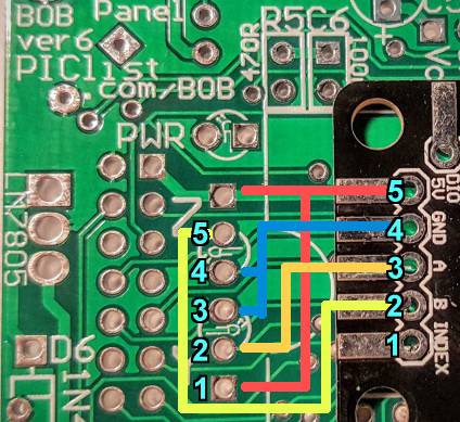
Quadrature Encoder:
[ ] Install a 1x6 (or 1x5, pins 6 & 1 share +5) header over the holes for the Z and Y LEDs. (see picture) The polarity tab should be towards the outside edge of the PCB and if a 1x5, it should be slid down to use the square pad toward the lower edge, near "D7" on the underside, of the PCB. See the picture below. This brings power, ground, and data lines originally for those LEDs out for a Quadrature Encoder; we can those data lines as inputs instead. The cable for the MassMind Encoder ENC2 is shown: (see also for ENC1)
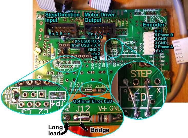
[ ] Install C4 (upper right corner, not shown in photo) and C7 (just left of U1 "PIC") to ensure stable power and avoid unexpected resets. Despite the value indicated on the PCB, C4 can be any good sized electrolytic capacitor (e.g. 220uF to 1000uF). Note it's long lead should be installed in the square pad nearest the "+" and just above and right of "C4".
[ ] Install JP4 and JP5 on the under side of the PCB, about an inch from the left, just below U1. See left bubble in picture.
[ ] Install a jumper over the RP2 LED network from STEP Y to the corresponding pin on the bottom side of RP2. See right bubble in picture.
[ ] Install a jumper sideways over RP2 from STEP A to the pin NOT directly on the other side of RP2, but one place over, towards the Y jumper you just installed. See right bubble in picture.
[ ] The PIC 18F14K22 is installed as U1 PIC on the bottom side center left. The notch on one end of the chip should match the notch on PCB and face the U1 PIC text. Be sure it is programmed first (Source code in github). The chip provided with the kit is already programmed and includes a bootloader for future firmware updates.
The PCB can be mounted to any surface with standoffs. The mounting holes are at these locations, measured from the left and bottom of the PCB (right, up)
ERROR FEEDBACK: OPTION. If you will want error feedback to your motion controller:
[ ] First be very careful that it can accept an error signal on pin 7 of the PMinMO connector. This pin is normally grounded, and so it will make any error much worse if we activate a short to ground. Connect a low value resistor over the "X" just above U1 on the underside of the PCB.
ERROR LED: OPTION. For an error indicator, this LED will light if the controller looses track of a shaft which is spinning too fast:
Install an LED with long lead in the A2D pin of J12 (lower edge of PCB) and the short lead in the hole just right of that. Keep the short lead long, and bend it over to also connect to J12 pin 1 (far right of J12) where a low value resistor (e.g. 330 to 560 ohms) should be installed with it's other lead in one of the GND pads of J11. (see center bubble in picture above)
TTL Serial 38400 N 8 2 X-ON/X-OFF: Connect a USB (or RS-232) to TTL serial converter to the J2 connector. e.g. FTDI Friend, RLC3 Again, pin 4 "TX" is data FROM the USB/Host going TO the PID controller. RX is TO USB/Host FROM PID controller. Configure your serial terminal program (e.g. Hyperterm, RealTerm, PuTTY, etc...) for whatever COM/TTY port shows up, and 38,400 baud, No parity, 8 data bits, and 2 stop bits. Select X-ON / X-OFF handshaking if available. Video
Note: The pre-programmed chips come with a bootloader installed. On power up, the serial connection will display a countdown in order to give time for the user to go into the bootloader mode if desired. Just wait for the countdown to finish for normal operation. If the screen fills up with "!" the magent isn't placed correctly.
Commands:
Start by entering very small values for pid. e.g. .01p.01i.01d then hit e to enable the drive and see if the motor moves at all. If not, try increasing p until the motor just moves a bit when you hit space and then e again or when you twist the shaft away from the home position. If you are getting up to 1p and the motor isn't turning, something is wrong with the enable or driver or wiring.
Once the motor starts turning, it may go in the wrong direction, which will make the error get worse and worse. Hit space, then put in 216w and enter then e again. If the motor still just spins, try space, 286w and e. The motor should just jump slightly when you hit e and should hold position loosely. E.g. you should be able to twist the shaft quite a bit and the motor should try to resist you a litte and move back to home. Enter 321w to save the settings.
Now increase p and tweak the motor shaft until it just starts oscillating. Set p to about half that value. Estimate the number of osciallations per second and set d to that frequency divided by 8. Set i to less than the frequency divided by 2. This is a good starting point. Continue with our PID Tuning / Troubleshooting page.
Source respository, Updating the firmware
Comming attractions (new features wish list). If you see something you really want, let us know.
See also:
/Techref/io/SERVO/BOBPID.htm Another typo on this page: To the right of where it says Step/Direction input from motion controller there is a box labeled X-axis Pin. It reads "Signal from BOB PCB" and it should say "Signal to BOB PCB" I think? I'm curious if the BOB PCB board is getting it's 5 volts from the grbl shield through the PMinMO adapter cable I purchased from you? I don't have your controller board working yet. The grbl shield works to drive steppers with a PMinMO driver in the socket but the drive I built from your kit has no lights lit when powered up. The error light on the BOB PID flashed for a second when motor power is applied. The BOB PID boards error light will also come on if I rotate the motor shaft by hand in either direction.James Newton of MassMind replies: I guess it makes more sense to have that say "to" instead of "from", thanks for the feedback. The BOB PID needs logic power from somewhere and it can get it from the DC motor driver, or from the motion controller or whatever.+
Questions:
| file: /Techref/io/SERVO/BOBPID.htm, 27KB, , updated: 2019/6/4 20:05, local time: 2025/10/17 08:11,
216.73.216.53,10-2-207-162:LOG IN
|
| ©2025 These pages are served without commercial sponsorship. (No popup ads, etc...).Bandwidth abuse increases hosting cost forcing sponsorship or shutdown. This server aggressively defends against automated copying for any reason including offline viewing, duplication, etc... Please respect this requirement and DO NOT RIP THIS SITE. Questions? <A HREF="http://www.massmind.org/Techref/io/SERVO/BOBPID.htm"> MassMind BOB PID Servo Motor Control</A> |
| Did you find what you needed? |
Welcome to massmind.org! |
|
The Backwoods Guide to Computer Lingo |
.