 |
Note: This page is for the original version of this encoder. It has been replaced by a new version 2
Based on the amazing AS5134
chip^,
this encoder supports 76875 RPM, 360 CPR/counts per revolution (with 4x decoding)
quadrature rotational encoding. It senses the position of a two pole radially
magnetized disk over a full revolution using a hall effect sensor array.
The sensor signal changes are converted to a digital quadrature signal, and
the position information stored as absolute position data on some registers,
which are readable through a 3 wire synchronous serial interface. Standard
quadrature Index, A and B phase signals are also generated just like any
standard encoder.
Features:
|
| Parameter | Min | Typ | Max | Unit |
| Supply Voltage | 4.5 | 5 | 5.5 | V |
| Current consumption | 30 | mA | ||
| Resolution (4x decoding) | 360 | cpr | ||
| Rated angular speed | 76875 | rpm | ||
| Accuracy | -3 | 3 | countsfs | |
| Weight | 0.12 (3.4) | oz (g) |
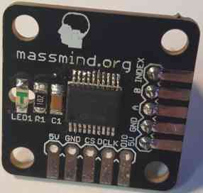
ENC2 Version:
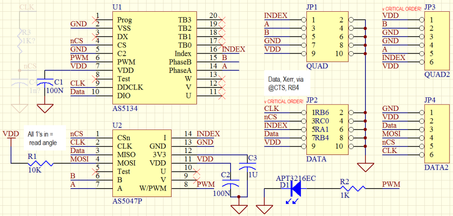
Original version:
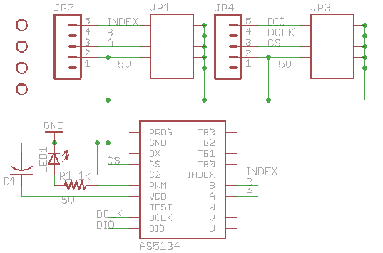
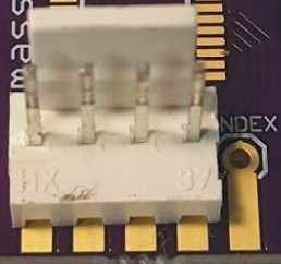
| Connector | Pin | Signal | Description |
| JP2 -Bottom (all even pins are ground) |
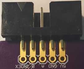
1 | Index | Incremental encoder index output. |
| 3 | B | Incremental encoder quadrature output. Channel A leads channel B by 90 degrees in clockwise rotation (top view). | |
| 5 | A | Incremental encoder quadrature output. | |
| 7 | GND | Ground pin for the board. | |
| 9 | 5V | Positive supply input for the board. | |
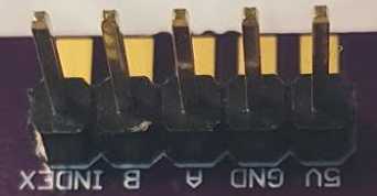
| JP4 -Side (all even pins are ground) |
1 | DIO | Data |
| 3 | DCLK | Clock | |
| 5 | CS | Chip Select | |
| 7 | GND | Ground pin for the board. | |
| 9 | 5V | Positive supply input for the board. |
The board supports multiple connector types:
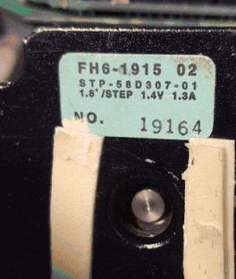
 PMinMO: A 2x5 header soldered on the edge with the PCB
inserted between the pins which are soldered along the face of the pads.
Used with a 10 conductor ribbon cable and IDC female 2x5 connector, this
option has the advantage of a ground line between each signal for very low
noise and long runs.
PMinMO: A 2x5 header soldered on the edge with the PCB
inserted between the pins which are soldered along the face of the pads.
Used with a 10 conductor ribbon cable and IDC female 2x5 connector, this
option has the advantage of a ground line between each signal for very low
noise and long runs.
To install a PMinMO shrouded header, slightly bend the pins in to match the PCB thickness, then align pin one (marked with the triangle on the shroud) with the pin marked "INDEX" on the edge of the PCB, The notch in the shroud should be on the top side of the PCB, where the chip is mounted. Solder a single pin, then check alignment and solder on the rest. To avoid overheating the plastic and warping the pin positions, solder one pin on the top, then the opposite pin on the bottom, alternating back and forth. It also helps to have a female IDC connector cable plugged into the header while soldering.
Single Row: A Molex KK or 1x5 header soldered through hole can also be used. In this case, it is good to use a polarized header so that it can not be plugged in backwards and a shielded cable for long runs.
Bare Wires: Or you can just solder the wires directly into the holes. Some strain relief, such as threading the wires through an unused mounting hole, would be wise.
Attach the magnet disk to the part where you need to sense angular position, e. g. front or back of the motor shaft, lead screw, ball screw, etc. The magnet should be mounted to the end of the shaft, flat against that end; a flat side of the magnet against the flat end of the shaft. For testing and alignment, the magnet will stick to any steel shaft, but vibration and shock will dislodge it. A two part epoxy is recommended for a permanent mounting. After placing the magnet, slowly turn the shaft to ensure it is centered and will not vibrate loose at higher speeds. The magnet is 0.100" thick and 0.235" diameter.
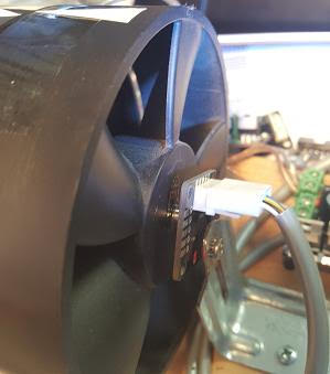
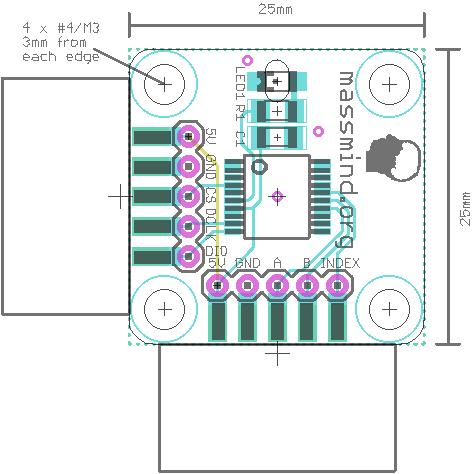
The board must be mounted so that the chip is close (less than a half inch) to the magnet and centered over the magnet’s axis of rotation.
The board supports M3 and #4 screws. At least two screws (diagonally) should be used to hold it in position. Three screws are best. Click the picture to right for a detailed mounting diagram.
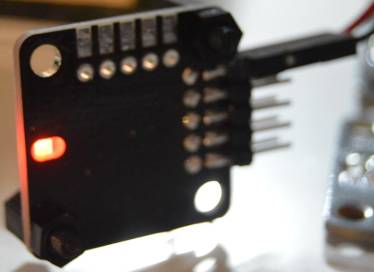
Turn the shaft where the magnet is attached. If the board is centered and close enough to the magnet, the onboard LED should dim and brighten as the magnet rotates in front of the IC. Note: If the encoder looses track of it's magnet, it will send invalid A and B phase signals as a way of letting the controller know it is out of reach.
The outputs from the ENC1 are standard quadrature encoder signals (Index, A and B phase).
In addition, there is a digital interface on the CS, DCLK, and DIO pins. The easiest way to use this is in "3 wire, read only" mode; basically SPI with MOSI always 0. (Note: Future versions of this encoder may remove the need for the CS signal)
Most often, the ENC1 will be used as input to a PID controller, such as the MassMind BOB PID.
See also:
Questions:
| file: /Techref/io/sensor/pos/enc/ENC1.htm, 10KB, , updated: 2019/6/17 14:34, local time: 2025/10/19 17:40,
216.73.216.53,10-2-207-162:LOG IN
|
| ©2025 These pages are served without commercial sponsorship. (No popup ads, etc...).Bandwidth abuse increases hosting cost forcing sponsorship or shutdown. This server aggressively defends against automated copying for any reason including offline viewing, duplication, etc... Please respect this requirement and DO NOT RIP THIS SITE. Questions? <A HREF="http://www.massmind.org/Techref/io/sensor/pos/enc/ENC1.htm"> MassMind Magnetic High Speed Non-Contact Encoder</A> |
| Did you find what you needed? |
Welcome to massmind.org! |
Welcome to www.massmind.org! |
.