Luc's TB6600 driver joins the other open source drivers supplied by the MassMind.org store, adding support for BiPolar (4, 6 or 8 wire) motors up to 4 .5 amps/phase at 50 volts. It is based on the new TB6600HG ( Datasheet ) chip which is a design improvment over the TB6560, adding support for higher power operation and protection for power on sequence^. This chip also provides it's own logic power supply so no +5 volt supply is required. The primary advantage is cost, as the chips are generally available for under $8 and a full driver can be less than $20. The chip supports microstepping up to 16 over; for smoother operation at higher speeds, with less resonance, check out the THB6064AH driver.
41607X 41607X 41607X
* These are electronics KITs, you need to solder them together.
  |
Features
|
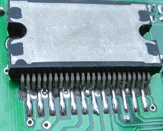
The chip is mounted under the PCB, with the fin (the part that will contact the heatsink) away from the PCB and the label of the chip up against the bottom of the PCB. Half of the pins (the longer ones including the first and last pin) are clipped off to remove the final bend at the end of the pin and the remaining length is inserted "through hole". The shorter pins are not clipped, but instead soldered surface mount style to the bottom of the PCB. This doesn't stress the pins, there's no slot in the PCB, and, due to the lack of the slot, routing is easier and a much better layout is possible: larger tracks and power planes.
The Honest Truth: It is a "chopper" type driver, so it doesn't require a terribly large heatsink, but you can expect to hear a little bit of motor "hiss" or "squeal" during operation (see the video below), and in high power systems, the motors may require more cooling than the driver. There are other drivers for different needs:
| Driver | Maximums |
Motors | Pros | Cons | ||
| Amps | Volts | Power | ||||
| Linistepper | 1 or 2, 3 max | 36 | <75 | 5, 6 or 8 wire Unipolar |
Ultra smooth, quiet, low mid band resonance, motor stays cool, cheap to repair | Limited power, driver heat |
| SLAm | 2 to 3 | 36 | 108 | 5, 6 or 8 wire Unipolar |
Stable, easy to build, small heatsink, tough | Resonance, motor heat/noise |
| THB6064 | up to 4 | 50 | 200 | 4, 6 or 8 wire Bipolar | Powerful, most motors (4, 6 or 8 wires), small heatsink, very tough | Some resonance, motor heat/noise |
| GeckoDrive.com (listed for compairison only) |
3.5-7 | 50-80 | 175-560 | Bipolar | Freaking magic | Cost $80-$166 per axis. |
Providing a range of drivers is in keeping with our "more is NOT necessarily better" approach. The same is true of motors: Unipolar motors cost less, provide less torque at low speeds, but maintain torque as speed increases. Bipolar motors, only when connected for parallel drive, provide better starting torque, but may not turn as fast and will generally be more costly. Pick the right motor for the job, based on your needs.
| Kit |
Part |
Qty |
Description |
|
41607X |
|||
| PCB | 1 | The printed circuit board only. Double sided, plated thru holes, professionally made. | |
|
41607y |
|||
| U1 | 1 | TB6600HG Bipolar 4.5A (5A peak), 48V Datasheet (pdf) | |
|
41607z Including the Chip and PCB listed above |
|||
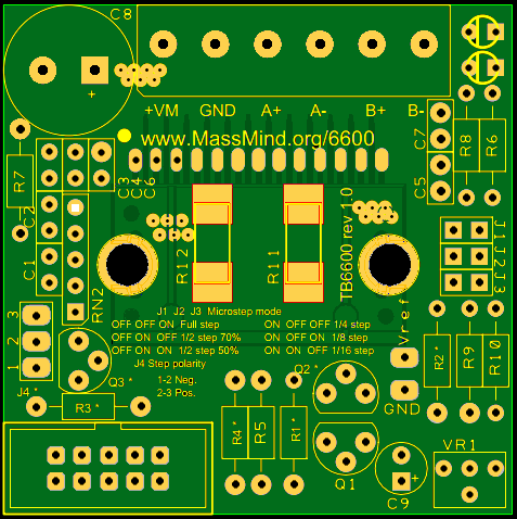
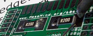
| R11,12 | 2 | 0.2 Ohm SMD 2W WSR2 Current sense | |
| VR1 | 1 | Potentiometer 5K Trim Current adjust | |
| R9 | 1 | 2K7 Ohm ¼W Current limit upper | |
| R10 | 1 | 470 Ohm ¼W Current limit lower | |
| C1-2 | 2 | 100p 6.3V | |
| C3-7 | 5 | 100n 50V | |
| C8 | 1 | 220µ 63V Electrolytic Motor Power Filtering | |
| CONN1 | 1 | 0.1" 2x5 Shrouded PMinMO w/Step, Dir, En and ground | |
| J1-3 | 1 | 0.1" 2 x 3 Header Mode select | |
| J6 | 2 | 0.2" 1x3 Terminal Block Motor / Motor & driver Power. | |
| RN2 | 2 | 10K SIP-6 Input / Reset pull up. | |
| R7 | 1 | 47K Ohm ¼W Osc2 | |
| Q1 | 1 | BC557 Automatic current reduction | |
| C9 | 1 | 1uF 6.3V Electrolytic Automatic current reduction | |
| R5 | 1 | 4K7 Ohm ¼W Automatic current reduction | |
| R8 | 1 | 4K7 Ohm ¼W Error LED current limit, LED will be dim, but a lower resistor will blow the output. | |
| LED1 | 1 | Red LED 3mm Error | |
| R6 | 1 | 330-2K2 Ohm ¼W Power LED current limit. | |
| LED2 | 1 | Green LED 3mm Power on indicator | |
|
Not Supplied: |
|||
| J4 | 1 | 0.1" 1x3 Header (not provided) Just short pins 1-2 for step on falling edge, 2-3 with "Step on Rising Edge" option shown below. | |
|
Options (not supplied): Components with a "*" next to the designator on the PCB are NOT required in most cases and are not supplied. |
|||
|
Step on Rising Edge Note that this option is not supplied with the kit, and is typically not needed. Step edge can be configured in software in almost every case and is generally not critical. This circuit reverses (and amplifies) the step signal. |
|||
| Q3* | 1 | BC547 | |
| R3* R4* | 2 | 1K0 Ohm ¼W | |
|
Amplified Error Reporting Note that this option is not supplied with the kit, and is a non-standard , use of the PMinMO connector to feed back an error condition to the PC or other motion controller. The error pin from the TB6600 has very limited drive strength. To safely drive an input back to a PC, it needs some amplification. For this option, R8 and LED2 are can be ommitted. The error signal will be routed to pin 7 of the PMinMO header by R1. |
|||
| Q2* | 1 | BC547 | |
| R1* | 1 | 47 Ohm | |
| R2* | 1 | 47K Ohm | |
 1.
Long lead in the square hole. Pin one or the positive lead is always marked
on our PCBs with a square hole. On components where pin one isn't marked
on the component package, the longer lead is always positive, and we make
that pad square on the PCB.
1.
Long lead in the square hole. Pin one or the positive lead is always marked
on our PCBs with a square hole. On components where pin one isn't marked
on the component package, the longer lead is always positive, and we make
that pad square on the PCB.
2. Don't solder the component in right next to the PCB; leave a little bit (1/4 inch, 1 mm) of lead.
a. This helps prevent the component from overheating when you solder, and during operation. It also gives you some lead to cut if you need to repair the board or if you get the component in the wrong hole. Trying to desolder the leads without cutting them is much more likely to damage the PCB.
b. To keep the components off the PCB, insert the leads so that the component is about a quarter inch up, then bend the leads together at that point, crossing them over each other at about 45 degrees. You could also bend them out, but then they would be in the way of the soldering iron, which is almost always coming in from the outer edge of the board. When you turn the PCB over to solder on the back side, the component will fall down to the point where the lead is bent, providing the correct spacing on the component side.
c. Solder one lead, stop and check the positioning and that it is the right component in the right place the right way around... then solder the other lead.
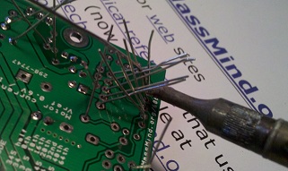
3. Work from the inside toward the edge, low components to high components. It's best to solder down any SMT components first, since they are certainly the lowest, then work up and out. Solder several components in a line if you can, then clip leads and do the next line.
4. It's important to clip all leads as short as possible to prevent shorts to the heatsink.
Keep the leads... they become the jumper for the power source and can be used for the test points.
 Passive
Components
Passive
Components
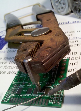
1. [ ] Surface mount Resistors. There are only two surface mount devices on this board, unless you count the driver chip as SMT because of the way it's being mounted. The components are large compared to most SMD and they really are easy to solder. The only trick is that there are no holes to hold the components in place by the leads, so you need some way to keep them in place while you solder. Almost anything that has 3 or 4 corners and won't melt can be used. A metal box, a heat sink, an aluminum extrusion, … anything. Probably the best is made from vice grips and a screw driver tip. If you don't have vice grips, wrap a rubber band around the far end of the handle of a pair of pliers. Or just tape one side of the part down with clear tape!
Once the part is held down in position, touch the pad, next to the end of the part, solder, flow, off. Solder one side of each part, check position, solder the other side.
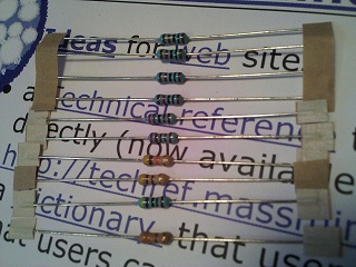
2. [ ] Resistors: There are several different values of resistors and a lot of the values look alike. Take care and be sure you have it right before you proceed. For example, there are 47K, 4K7, and 470. And there is a mix of 4 and 5 band resistors (low and high precision). Getting them right is harder than you think, certainly harder that soldering surface mount components. An amazing percentage of people are, at least partially, color blind. Some don't know it until they start trying to sort out resistors. And even if you aren't, it takes a strong light and good luck to tell orange from gold or brown from purple on some of these packages.
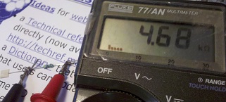
We strongly recommend using a multimeter to check the values of the resistors rather than reading the color codes. When using a meter to read resistance, be sure not to let your fingers touch both leads. In other words, one test lead should be held to the resistor lead by a clip, or by pressing it against a surface and NOT by holding the two together with your fingers. Otherwise, the reading can be off due to the lower resistance path offered by your skin.
If you must read the bands, start by arranging them with the colorful bands to the left. In most cases, that will give you the correct order, with the tolerance band on the right and the actual value reading from left to right. There are exceptions. The 5 band 10K resistors currently supplied with the kit are brown, black, black, red, brown (1, 0, 0, two more zeros, and a 1% tolerance). Read it each way, figure out which one makes more sense given the resistors in the set... and then check it with your meter. Really... For less than $25 you can get a half way decent digital multimeter (watch out, it doesn't include the special battery) from your local Radio Shack right now or order one from eBay china and wait a month for it to show up. Believe it or not, WalMart (gag) sells a pretty good one in most of their stores: The "Equus 3320 Innova" for less than $20.
R6 has a non-critical value and different values may be supplied. Install the others first and what ever is left over is probably R6.
3. [ ] Variable Resistor: This is the drive current adjustment. It can be installed either way but being able to get in there to turn it is the trick. Make sure you will be able to get to it after installing the other components. It's probably best to install it facing the edge of the board. Take care not to melt the case by letting each lead cool a bit after soldering.
If you like, you can even bend the leads on the variable resistor and install it flat agasint the PCB, with the shaft up. It will just hang a bit over the edge that way.
4. [ ] Network Resistor: It's all about the dot. Network resistors all have a (very tiny, dimly printed, very hard to see) dot at one end, usually down next to the pin. That pin is pin 1 and pin 1 goes in the square hole. Bend the outermost pins out so it won't fall down when you turn it over to solder it. Then push the pins back down so they are just through the hole so you leave a little lead on the component side. Solder one pin, check positioning, and solder the rest.
5. [ ] Capacitors: The little capacitors will be marked with a number: 101 or 104 which represents the first two digits and the number of zeros in pico Farads. "101" is 100pF. "104" is 100000pF or 100nF or 0.1uF.
The bigger electrolytic caps go in with the long lead in the square hole, and the stripe side towards the round hole. It's probably best to set those aside and come back to them after you have done all the other components. And the really big one is an exception to the "leave some leads" rule. It can be installed all the way down on the PCB for physical stability.
6. [ ] LEDs: The long lead goes in the square hole, leave a little lead so the LEDs are up off the PCB and where you can see them. The Red LED is in the far upper right corner, with the green power LED just down the board below it. You may wish to stick a bit of electrical tape or plastic between the LEDs to prevent the green one shining into the red and making you think there is an error. Black marker also works well. If you want to feed back the error signal to your controller see the Option for Amplified Error Reporting in the parts list above; this is not recommended.
7. [ ]
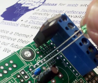
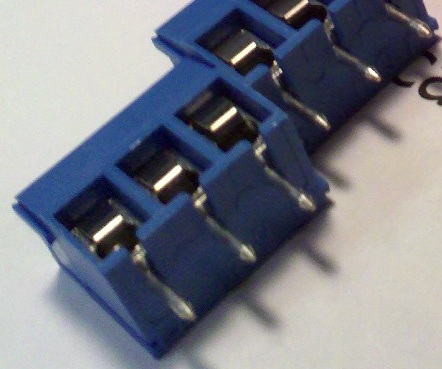 Terminal
Blocks: Slide the two sets of terminal blocks together so that the rail
and groove interlock. Place them in the PCB with the openings for the wires
to the outside of the PCB. This is important to get right because desoldering
these is very difficult.
Terminal
Blocks: Slide the two sets of terminal blocks together so that the rail
and groove interlock. Place them in the PCB with the openings for the wires
to the outside of the PCB. This is important to get right because desoldering
these is very difficult.
8. [ ] Jumpers: When you solder on the 2x5 header for the options jumpers and the shrouded 2x5 PMinMO header, it's a good idea to bounce around in the pin order rather than just going down the line. It keeps the plastic from getting soft and perhaps not holding the pins straight.
Note the notch in the shrouded header is towards the inside of the PCB, away from the edge.
9. [ ] Use one of the clipped resistor or other component leads to short pins 1 and 2 of J4 on the right lower edge of the PCB.
10. [ ] Test Points: Form loops from a couple clipped leads and push both ends into the hole for the VREF test point and the GND test point.
11. [ ] At this point, without the chip installed, do a visual inspection, preferably with a magnifying glass. If you have a regulated 5 volt power supply, you might want to apply logic power at the square pad of the error LED in the far upper right corner of the PCB. The +5v led should be on and the Vref can be measured and adjusted to a low value: 0.4-0.5V. Power off and prepare for finally assembly.
12. [ ] The big TB6600 chip: Since this product has a MOS structure, it is sensitive to electrostatic discharge. These ICs are highly sensitive to electrostatic discharge. When handling them, please be careful of electrostatic discharge, temperature and humidity conditions. Wear a grounding strap when touching the chip and work on an anti-static surface.
Luc's method of mounting the chip is a bit unique:
The chip is mounted under the PCB, with the fin (the part that will
contact the heatsink) away from the PCB and the label of the chip
up against the bottom of the PCB. Half of the pins (the longer ones including
the first and last pin) are clipped off to remove the final bend at the end
of the pin and the remaining length is inserted "through hole". The shorter
pins are not clipped, but instead soldered surface mount style to the bottom
of the PCB.
- [ ] Clip the long pins just before the final bend. Bend them slightly up so they go straight through the holes in the PCB.
- [ ] Make sure the "surface mount" pins are flat on the pads so the solder will flow nicely over the length of the pin and form a strong connection.
- [ ] Make sure the two large mounting holes either side of the chip align with the holes in the PCB.
- [ ] Solder one "surface mount" pin by placing the tip of the iron on the pad near the pin and let the solder flow around and under the pad. Check placement, alignment, and orientation and then solder down the rest of the flat pins. It's a good idea to bounce around and pause once in awhile to keep the heat from building up in the chip.
- [ ] Now go back and solder the through pins from the top of the PCB. Make sure you don't get too much solder through the hole to the back side.
- [ ] Mount the chip and PCB to the heat sink using 3 #4-40 or M3 screws. Drill and tap for M3 or #4-40. Do a dry fit with just the screws.
- [ ] Finally, reassemble with a bit of heatsink paste under the chip. That paste makes a huge difference in high temperature operation.
The IC fin is electrically connected to the rear of the chip. If current flows to the fin, the IC will malfunction. If there is any possibility of a voltage being generated between the IC GND and the fin, either ground the fin or insulate it. We recommend that you directly connect the IC to the heatsink, and ground the heatsink.
Questions:
| file: /Techref/io/stepper/tb6600/index.htm, 23KB, , updated: 2018/11/5 11:57, local time: 2025/10/17 12:57,
216.73.216.53,10-2-207-162:LOG IN
|
| ©2025 These pages are served without commercial sponsorship. (No popup ads, etc...).Bandwidth abuse increases hosting cost forcing sponsorship or shutdown. This server aggressively defends against automated copying for any reason including offline viewing, duplication, etc... Please respect this requirement and DO NOT RIP THIS SITE. Questions? <A HREF="http://www.massmind.org/Techref/io/stepper/tb6600/index.htm"> TB6600HG MassMind.org Stepper Motor Driver</A> |
| Did you find what you needed? |
Welcome to massmind.org! |
|
Ashley Roll has put together a really nice little unit here. Leave off the MAX232 and keep these handy for the few times you need true RS232! |
.