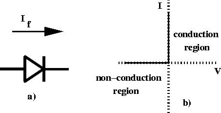
Figure 4.4: a) Schematic symbol for a diode and b) current versus voltage for an ideal diode.
Diodes are referred to as non-linear circuit elements because of the above characteristic curve. For most applications the non-linear region can be avoided and the device can be modeled by piece-wise linear circuit elements. Qualitatively we can just think of an ideal diode has having two regions: a conduction region of zero resistance and an infinite resistance non-conduction region. For many circuit applications, this ideal diode model is an adequate representation of an actual diode and simply requires that the circuit analysis be separated into two parts: forward current and reverse current. Figure 4.4 shows a schematic symbol for a diode and the current-voltage curve for an ideal diode.

Figure 4.4: a) Schematic symbol for a diode and b)
current versus voltage for an ideal diode.
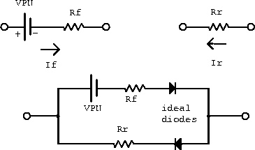
A diode can more accurately be described using the equivalent circuit
model shown in figure 4.5.
If a diode is forward biased with a high voltage it acts like a
resistor ( ![]() ) in series with a voltage source (
) in series with a voltage source ( ![]() ).
For reverse biasing it acts simply as a resistor (
).
For reverse biasing it acts simply as a resistor ( ![]() ).
These approximations are referred to as the linear element model of a
diode.
).
These approximations are referred to as the linear element model of a
diode.

Figure 4.5: Equivalent circuit model of a junction diode.