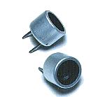
 I used the ultrasonic sensor for the air which is made by the Nippon Ceramic company. This sensor separates into the two kinds for the transmitter and the receiver. For the transmitter, it is T40-16 and for the receiver, it is R40-16. T shows the thing for the transmitter and R shows the thing for the receiver. 40 shows the resonant frequency of the ultrasonic.(40kHz) 16 shows the diameter of the sensor. I used the ultrasonic sensor for the air which is made by the Nippon Ceramic company. This sensor separates into the two kinds for the transmitter and the receiver. For the transmitter, it is T40-16 and for the receiver, it is R40-16. T shows the thing for the transmitter and R shows the thing for the receiver. 40 shows the resonant frequency of the ultrasonic.(40kHz) 16 shows the diameter of the sensor.Because the one of the terminal is connected with the case, when grounding, the terminal on the side of the case should be used. 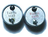 The brief specification of the ultrasonic sensor is shown below.
As for the detail specification, refer to "Air Transmission Ultrasonic Sensor".  In the circuit this time, capture feature and A/D converter feature are used.  This IC is the low noise operational amplifier. It is used for the amplification of the received ultrasonic signal. The low noise type operational amplifier should be used because it does the about 60dB (1000 times) amplification.  This IC is the single power supply-type operational amplifier. This IC is used for the detection of the received signal. The comparator can be used.  As for this IC, the four NAND circuits of 2 inputs are accommodated. It is used to compose SR-FF and to hold the detection condition of the ultrasonic.  This IC is the IC of the CMOS which the six inverters are housed in. At the transmitter circuit, it is used for the drive circuit of the ultrasonic sensor.  This regulator is used to make the stable power of +5V. The maximum output current is 1A.  The stable +9V can be gotten from +12V input by this IC. The maximum output current is 100 mA.  This is the transistor to drive the C-MOS inverter which works at 9V with the output of PIC. The output of PIC is from 0V to 5V. This transistor converts into the voltage from 0V to 9V to control the inverter.  This transistor is used to control the 7 segment LED. PNP type is used for controlling the anode side of the LED. 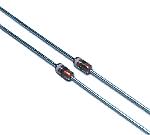 These diodes are used to detect the received ultrasonic. The ultrasonic frequency is about 40KHz, so, the diode with the good high frequency characteristic is used. 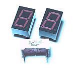  I use SL-1199 made by Sanyo Electric Co in Japan. The size is 18.8mm(H) x 12mm(W) x 8mm(D). 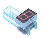 I assumed that a range meter was put in the case and made an LED installation stand. It is the one to have bent a 2-mm thickness acrylic board. It has 11mm(H), 40mm(W), 13mm(D). Because the thickness is 2 mm, the board is the following size.
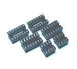 PIC16F873 is 28 pins of the slim type. When you can not get a slim-type 28 pin socket, two sockets of 14 pins can be used. In the circuit this time, I used two 14 pin sockets. 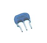 I used 4-MHz resonator. At the circuit this time, the timer value is important and can not be used except 4 MHz. 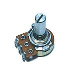 I used B type. 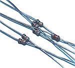 I used 1/8W as all resistors. 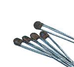 These are the disk-type ceramic capacitors. Because the high frequency characteristic is good, these are used as the coupling capacitors(It cuts the direct current but it lets through the alternating current) of the ultrasonic signal amplification. 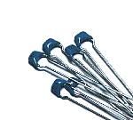 These capacitors are used to bypass the high frequency noise of the input and output of the power supply. 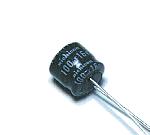 This capacitor is used as the ripple filter capacitor of the power circuit. There is polarity. So, Be careful so as not to make a mistake when mounting it.  I used the universal board with the 25 x 30 holes. 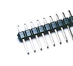 This terminal is used to connect power supply wire and wire for the variable resistor for display proofreading. 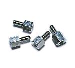 These studs are used to install the equipment in the case. |
|||||||||||||||||||||||