Parts explanation
for DC motor speed controller
 In the circuit this time, PIC16F873 is used. At the circuit this time, the control of the drive electric current of the motor is done using the PWM function of the CCP. The voltage according to the number of rotations of the motor is taken in to the analog-to-digital converter and has the control of the drive electric current. This time, it is using a motor for the speed detection. Also, LEDs for the monitor are lit up to know the situation of the motor drive.  This regulator is used to make the stable power of +5 V. Eight LEDs for the monitor sometimes light up at the same time.(This time, it is seven) So, when using a 100 mA-type regulator, little leeway occurs. This time, a 1A type is used for the safety.  This transistor is used to drive MOS FET by the output of PIC. It is converting the output of PIC (0V to 5V) into the voltage to control an FET (0V to 12V).  This is N channel MOS FET. The maximum drain current is 60A. When the FET is in the ON condition, the resistance between drain and source is 4 milli-ohm. So, the electric power loss when the 10-A electric current flows in the ON condition is 0.4 W. The circuit this time doesn't have to use an FET with such big capacity. It is because I don't have an FET with appropriate capacity.  The voltage which is applied to the terminal of PIC is a maximum of +5V. This diode prevents the destruction of PIC when the speed detection voltage of the motor exceeds 5V. When more than +5V voltage be applied never from outside, it is unnecessary.
 I put the silicon diode bridge not to be in the problem even if it connected the pole of the motor for the speed detection oppositely. When never making a mistake in the connection, it is unnecessary. 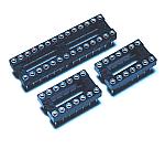 PIC16F873 is 28 pins of the slim type. When you can not get a slim-type 28 pin socket, two sockets of 14 pins can be used. In the circuit this time, I used two 14 pin sockets. 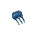 I used 10-MHz resonator. When changing the frequency of resonator, the value with all kinds on the software must be changed. 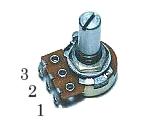 I used B type. At the circuit this time, terminal numbers are used like the figure on the left. It becomes low-speed when turning to the left and it becomes high-speed when turning to the right. There is a circuit which is using oppositely in the position of the No.1 terminal and the position of the No.3 terminal. The one is general. 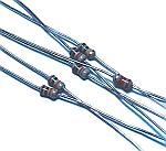 It is to be OK at 1/8 W.  These capacitors are used to bypass the high frequency noise of the input and output of the power supply. 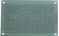 This is an universal printed board with 15 x 25 halls. At first, I planned to use connectors to install LEDs and a variable resistor for the motor speed setting at the lid of the case. However, because it isn't possible to house in the case, I decide to use wiring terminals. 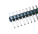 This terminal is used to connect a power supply wire and load. 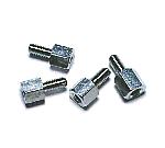 This is used as the leg of the printed board. 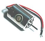 This is the motor which drives with the circuit this time. I use RS-380PH made by MABUCHI MOTOR Inc. in Japan. The specification of this motor is shown below. This is the motor which drives with the circuit this time. I use RS-380PH made by MABUCHI MOTOR Inc. in Japan. The specification of this motor is shown below.
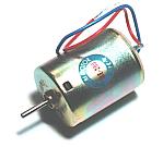 At the circuit this time, speed detection of the main motor is done with the motor for the detection. I use RE-280 made by MABUCHI MOTOR Inc. in Japan. The specification of this motor is shown below. At the circuit this time, speed detection of the main motor is done with the motor for the detection. I use RE-280 made by MABUCHI MOTOR Inc. in Japan. The specification of this motor is shown below.
When making turn at the speed which is the same as the main motor, it exceeds above-mentioned specification. The generated voltage exceeds a specification but I think that there is no problem because the electric current flows hardly. Strictly, there is a problem of the insulation because it becomes above the specification voltage. However, I seem not to be in the hinderance because it is not high voltage. 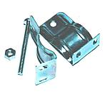 The motor is a cylinder and a screw for the motor fixation is put to the front. When installing a motor on the panel and so on, you can use these holes. This time, I used the installing metal fittings of the type which inserts a motor. The motor is a cylinder and a screw for the motor fixation is put to the front. When installing a motor on the panel and so on, you can use these holes. This time, I used the installing metal fittings of the type which inserts a motor.
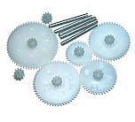 These gears are used for the connection between the main motor and the motor for the speed detection. This time, because it is for the operation confirmation of the speed control of the motor, the main motor is turning only a motor for the speed detection. 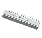 This is the LED for the bar graph displaying which seven LEDs were incorporated into. The control circuit can control eight LEDs. Because the indicator with eight LEDs could not be gotten, I decided to use the indicator which had seven LEDs. However, when using as the level meter, the needed LED is seven. This is the LED for the bar graph displaying which seven LEDs were incorporated into. The control circuit can control eight LEDs. Because the indicator with eight LEDs could not be gotten, I decided to use the indicator which had seven LEDs. However, when using as the level meter, the needed LED is seven.
 This is the terminal which connects a main motor and a speed detection motor. 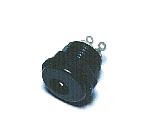 This is the connector to connect a power. 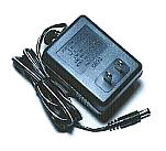 At first, I planned to share the power of the main motor. However, the power of the motor separated from the control unit because it depended on the kind of the motor. This adapter is for the control unit. 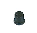 This is the knob to turn a variable resistor for the speed control. 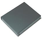 I used the case which is made from metal for MOS-FET for the motor drive. In case of the motor which drives this time, the consumption electric power in MOS-FET for the drive is little. So, I think that it is OK even if it puts or it doesn't put a small heat sink depending on the size of the drive electric current. I used TC-4 which is made by the TEISHIN electronics Inc. in Japan. It is made from aluminum with 75mm width, 95mm depth, 20mm height.  I made a panel to display the name of the power connector and the motor connection terminal. I printed a panel to the OHP sheet. Then, I put white paper behind the OHP sheet for the character to be able to be well seen.
 I put a name plate as the ornament. 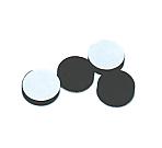 This is the leg to put to the case which was made of rubber. This leg is the attachment of the case.  I put a terminal cover to the drain terminal (center) of the FET. It is to prevent from touch with the terminal next. |