Little blocks with an input end and and output end. When you cover the input, the output flashes rapidly. When light strikes the input, the output is suppressed. If you place two outputs up against one input:
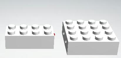
Then you have made a two input NAND. Which is the basic building block of all logic circuits.
AND:
- You can SEE the logic levels at each chip
- It won't react to ambient light levels since only pulses of light affect it.
- Inputs can come from anything that interrupts the beam of pulses from a logic brick with its input plugged. Flags or mirrors can be attached to motor shafts, button, levers, bumpers, etc..
- Rather than a solid on / off, they could be set to react more strongly to a stronger signal. There are some interesting "analog logic" possibilities.
The biggest problem with this is the power supply. They could be run by coin cells, but that would be a pain to keep replacing, a substantial cost in the long run, and would increase the minimum size of each block.
Solar power / Analog?
Starting with the SolarBotics.com
BEAM
Photovore
Photopopper kit:
http://downloads.solarbotics.com/PDF/kit2.pdf
| 2N3904 1 | Standard NPN Transistor | TO-92 |
| 2N3906 1 | Standard PNP Transistor | TO-92 |
| Panasonic 1381-Cx 1 | voltage detector. 2.0 volts active high Versions trip at 2.0 to 4.6 volts |
TO-92 or "Mini" SM (2.9mm2 |
| Siemens SFH 205f 1 | Wide Field of View Infrared Photodiode Detector | |
First, we reduce the size of the PV panel or convert to an induction coil and rectifier for power.
Second, we replace the Motor with an LED.
Third, we capacitivly couple the photodetector so that it only passes on pulses of light.
Finally, the circuit gets compressed to SMT levels and shoved into a lego brick with the photodiode at one end and the LED at the other.
When the photodiode is activated by pulses of light from another source, the LED will be suppressed and will not flash. Increasing the .22uF cap may help to smooth out incomming pulses and prevent triggering between flashes. In general, there will be some frequency at which the input will appear constant to the circuit and will suppress the "neuron"
When enough charge has accumulated from the solar panel or other power source, if the input is not suppressing the circuit, the output will fire a pulse. The 2N3906 is included to keep the 2N3904 on until all the available power is used, and by removing this circuit, we may be able to get a series of flashes rather than one long burst.
Digital
It may be that a digital system would allow for more flexability. For example, the function of the gate could be changed to become a more complex block, like a flip flop, or with additional inputs and outputs, a latch, register block, program memory, ALU, microcode, etc...
It might also be possible to look for meta data in the input light stream, such as a request to describe layout. If each block has a serial number, then the topography of the circuit can be read out by the circuit into a special board that connects to a PC and then translates into VHDL for an FPGA.
Other metadata might reconfigure the operation of the blocks. E.g. changing from a NAND into a flipflop.
Data could also be multiple bits of data, so one beam of light could cary a 4 or 8 bit bus. Although that removes the ability of the user to visualize the flow of data through light.
It might be best to make one PCB with space for 4 SMT LEDs on the input and 4 on the output. For the standard NAND gate, only 1 of the 4 on each side needs to be populated, but for more complex (up to 4) blocks, all the LEDs could be populated.
Also: Computer Hardware Memory with Neon Lamps
See also:
Questions:
"J. L. Patterson, Will Neon Photo-conductors Replace Relays in Low-Speed Logic?, Electronics, 36:18 p 46-49."+
I have built similar nor gate arrays and routed the light using vinyl cord from the craft store.
Fun stuff!
Could also be made with one of the small, very low cost uC, like the AT tiny, or the PIC18F14K50. The board could be programmed via a USB pads on one end and could run from a small PV panel, harvested RF (which might also be used to detect RF fields), or a coin cell (paper clip soldered in bent as a holder). LED's can be used for input and output. +
| file: /Techref/idea/logicblocks.htm, 7KB, , updated: 2017/1/3 16:11, local time: 2025/10/26 01:43,
216.73.216.180,10-8-63-169:LOG IN
|
| ©2025 These pages are served without commercial sponsorship. (No popup ads, etc...).Bandwidth abuse increases hosting cost forcing sponsorship or shutdown. This server aggressively defends against automated copying for any reason including offline viewing, duplication, etc... Please respect this requirement and DO NOT RIP THIS SITE. Questions? <A HREF="http://www.massmind.org/techref/idea/logicblocks.htm"> Lego Logic Blocks / Optical NAND</A> |
| Did you find what you needed? |
Welcome to massmind.org! |
|
The Backwoods Guide to Computer Lingo |
.