How to build the Linistepper Version 2!
NOTE: This version is no longer available. Please use
the Version 3 Instuctions for the new
kit. (Instructions for Version 1 are
also available)
You need the usual small electrical tools and soldering iron with FINE tip,
preferably temperature controlled. Although assembly is very simple and clearly
laid out, it is expected that you have good soldering skills and some experience
with closely packed circuit boards.
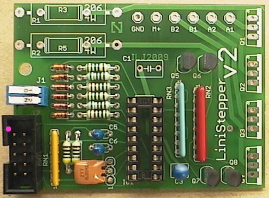
Review the board layout and schematic. (note: The current V2C is effectivly the same as V2B)
Parts List
Part No. |
Specs |
QTY | Description |
|
|---|---|---|---|---|
| PCB | LiniStepper v2 | 1 | PCB | |
| R1, R2 (see website) | 1 ohm, 5 Watt | 2 | resistor (big white) - (website describes fine tuning to suit your needs) | |
| R4, R6 | 470 ohm, 0.6W | 2 | resistor - yellow, purple, black, black, brown(1%) | |
| R18, R21 | 150 ohm, 0.6W | 2 | resistor - brown, green, black, black, brown(1%) | |
| R19, R22 | 680 ohm, 0.6W | 2 | resistor - blue, gray, black, black, brown(1%) | |
| R20, R23 | 220 ohm, 0.6W | 2 | resistor - red, red, black, black, brown(1%) | |
| D1-D6 | IN4148 | 6 | signal diode (glass) | |
| RN1 | 3k3 ohm, 6 pin | 1 | resistor network - |
|
| RN2 | 3k3 ohm, 8 pin | 1 | resistor network - |
|
| RN3 | 120 ohm, 8 pin | 1 | resistor network - |
|
| C1 | 470uF, 35v | 1 | electrolytic capacitor (light green) | |
| C3 | 10uF, 25v | 1 | tantalum capacitor (dark blue) | |
| C5, C6 | 2.2uF, 35v | 2 | tantalum capacitor (dark blue or dull yellow) | |
| IC1 | PIC 16F628A | 1 | PIC 16F628A, 18 pin | |
| IC1 - socket | IC socket | 1 | 18 pin IC socket | |
| SV1 | 16MHz, 3 pin | 1 | 16MHz ceramic resonator (orange) | |
| J1, J2 (set step mode) | DIP switch | 1 | DIP switch - 2 way (blue) - (used to select the step mode) | |
| SV3 | IDC socket | 1 | IDC socket - 10 way (black) | |
| GND,M+,A1,A2,B1,B2 | wire connect | 3 | 2 way wire terminal - join into 6 way before soldering (green) | |
| Q5,Q6,Q7,Q8 | BC337 | 4 | transistor NPN (e.g. BC337 or equivalent) | |
| Q1,Q2,Q3,Q4 | TIP122 | 4 | TO220 transistor NPN, darlington | |
| Mica washer | (for TIP122) | 4 | TO220 mica washer | |
| Insulator | (for TIP122) | 4 | TO220 bush/insulator | |
| Bolts - 3mm | (for TIP122) | 4 | 3mm diameter, 10mm long, for heatsink securing | |
| Nuts - 3mm | (for TIP122) | 4 | 3mm diameter, for heatsink securing | |
| Heatsink goop | (for TIP122) | 1 | for good heat dissipation |
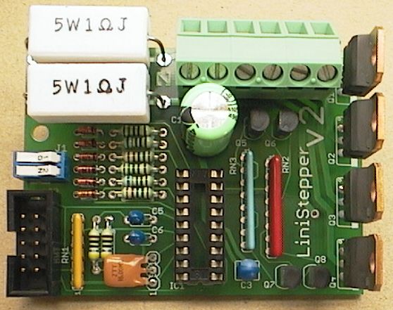
Refer to the PCB overlay diagram above for the resistor values. (In the photo below the resistor colours have been emphasised and written next to each resistor). Take care not to get solder in the empty holes nearby (e.g. for the diodes) when soldring the resistors. You might want to insert all the diodes and the resistors before soldering any of them.
All 6 diodes go the same direction, the black stripe faces towards the resistors. Pre-bend the diode legs before inserting, the legs must be bent as close as possible to the body of the diode so they fit neatly in the PCB holes.
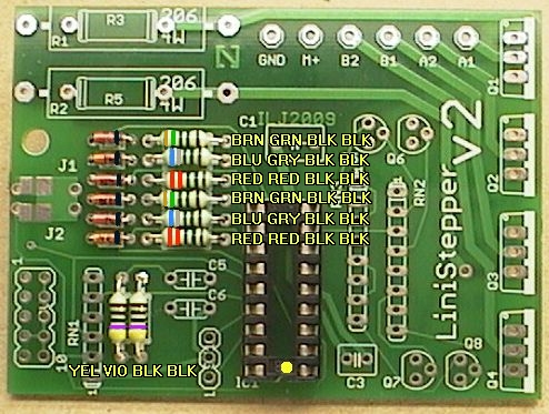
The PIC socket must be inserted the correct way around!
It's notch must be facing the edge of the PCB, see the dot (near the bottom of photo).
Do the 3 resistor networks first. These are the long ones with a row of straight pins.
They must be inserted the correct way around! Check with the PCB overlay at the top of the page. There is a dot at one end of each resistor network, this marks pin 1. These are shown with a "X" in the photograph below.
RN1: 3k3 6pin (6X-1-332 YELLOW) (A332J short) network
has pin 1 at the bottom edge of the PCB.
RN2: 3k3 8pin (B332A RED) (8X-2-332) has pin 1 at the top
(writing is hard to see!)
RN3: 120 ohm 8pin (8X-2-121 PALE BLUE) (B121G long) has
pin 1 at the top.
It can be hard to tell RN2 and RN3 apart. Originally they were different
colors, but the colored versions are no longer available. Instead, look for
"121" in the part number printed on RN3 and "332" in the part number on RN2.
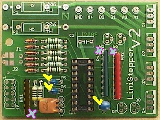
Next insert and solder the tantalum capacitors. The tantalums MUST be inserted the correct way around. They are marked with a tiny + sign near the + lead. The positive lead is usually on the right when looking at the writing. The + lead must go on the side marked with the check mark in the photo; the side toward the RN1. Gently scrape the leads to make them shiny and easier to solder (if they are dull). The two smaller tantalums are 2.2uF and go together (see photo, C5/C6). (BLUE in the photo, may be YELLOW in the kit) The larger tantalum is 10uF 25v. C3 (BLUE in the photo, may be ORANGE in the kit)
Next is the 16MHz ceramic resonator (ORANGE). It is a bit tall and fragile, and is best laid down. First bend its legs GENTLY with small pliers, then insert and solder it.
Insert and solder the 10 pin IDC cable connector (black). It is usually soldered as shown in the photo. It's pin 1 is shown marked with a dot. You may wish to leave off this connector and wire a cable directly to the holes in the Linistepper V2 PCB. If you are using a PNinMO break our board, this connector matches perfectly. If you are using a 4Axis board, the 4 Axis ribbon cable connects between this connector and the large header on the 4Axis PCB. Note that the power and ground wires may not be in the same order on the 4Axis connector.
The orientation of this plug relies on the fact that the device you are connecting the OTHER end of the cable to has it's plug oriented correctly. Pin 1 on BOTH ends of the cable should be the RED wire if you are using ribbon cable. If you use individually stranded cable, check carefully to ensure each pin connects to the correct signal.
Next insert and solder the 2-way DIP switch (BLUE with WHITE switches). The switches marked 1 and 2 should be the same as the J1 and J2 marks on the PCB.
Now insert and solder the 4 BC337 (small black) transistors. These should be inserted so they match the symbol shown on the PCB. Leave them free standing about 6mm (1/4") above the PCB to reduce strain on their legs.
Next assemble the (green) screw-down connector. This comes in 3 parts.It is important to slide these 3 parts together in exactly the right way. They have 2 tiny "key-ways" on each side. You must SLIDE them together correctly!
They are hard to connect (it takes strong fingers!) but they are a quality connector and when joined there is no air gap visible between them, and they lock together solid to make one 6-way connector.
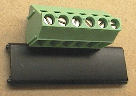
Finally tap them on a piece of plastic (or a plastic ruler) to make sure they are lined up straight. Insert and solder the 6-way screw-down connector. The wire entry holes must be on the outside edge (top) of the PCB. See the photo in the next step.
Next do the 470uF electro cap C1. This must be inserted so it's + pin (with the longer lead) faces to the right, see the X on the photo below. The other side of the cap is marked with a large black stripe to indicate the - pin. The black stripe goes toward the mode switches, the long lead goes towards the power transistors. You might want to solder it in with a little bit of lead between the cap and board so that you can bend it out of the way of the terminal block.
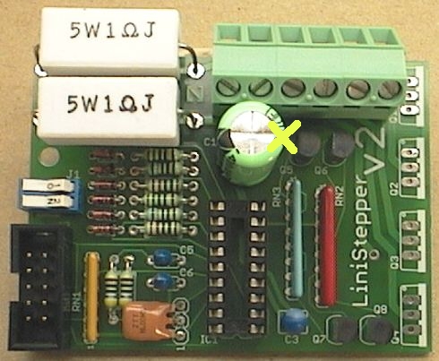
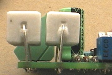
Now do the two (big white) 1 ohm 5w resistors R1 and R2. These should be spaced well above the PCB for cooling and to reduce strain on their leads. Mount them about 6mm (1/4") above the PCB. Also space them slightly apart to improve air cooling, about 3mm (1/8") apart is good. See the next photo.
If you have the new V2B or V2C or later version of the PCB, skip this step. If you have the V2 PCB (without the little subscript letter after the big V2 on the PCB) you must cut a trace and add a small jumper wire on the bottom of the PCB. This change connects the 2-way DIP switch to +5v instead of to Ground. Cut the track connecting the DIP to ground; see the dot just to the left of the lower end of the jumper wire where there is a circular mark left by the mill used to cut the track in this photo. You MUST cut this track if it hasn't already been cut! Installing the jumper wire when this track is intact will result in a full power supply short which could destroy your 5 volt supply. Use a knife, dremel, or other cutting or grinding tool to break the track.
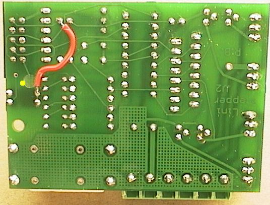
Next prepare a little wire about 28mm long (1.2"). Solder this as shown in the photo. The top end of the wire joins to +5v (taken from resistor R4) and the bottom end of the wire joins to the rear connection (common) of the DIP switches. Again, if you have the new V2B version of the PCB, skip this step.
Note! Please read Steps 7, 8 and 9 BEFORE soldering Q1-Q4.
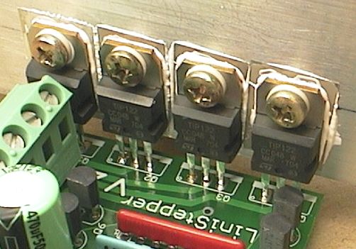
The last step is to insert and solder the 4 main TIP122 power transistors Q1-Q4.
NOTE! Before soldering the power transistors, do some checks of your heatsink setup. Once these 4 transistors are soldered into the PCB it is very hard to move them!
Have a think about your final setup and where the PCB will be mounted relative to the heatsink.
It's probably best to drill the 4 holes in your heatsink first, then mount the 4 power transistors with the insulating washers and heatsink goop BEFORE doing the soldering.
(Check Step 8 "Insulating" for details.)
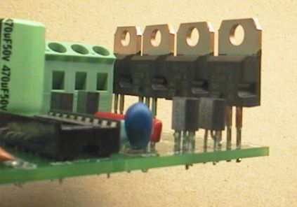
Keep in mind the 4 power transistors should be mounted about 10mm (3/8") above the PCB, this allows better clearance to get a screwdriver onto the transistor mounting screws.
It also allows some "give" in the transistor legs to allow for heat expansion and positioning. See the photo below.
The 4 power transistors Q1-Q4 MUST be insulated from the heatsink. This means the transistor bodies and metal tabs are NOT electrically connected to the heatsink.
Use the clear Mica insulating washers, these go between the transistor body and the heatsink (see '1' in the diagram below). You MUST put heatsink goop on both sides of the Mica washer, this only requires a tiny smear in the middle (which will squish flat when tightened down).
There is also a plastic insulator (see '2' in the diagram) this stops the metal screw touching the metal tab of the transistor. No heatsink goop is required on the screw.
It is OK for the metal screw to touch the heatsink. In fact you may prefer to use self-tapping 3mm screws if your heatsink metal is very thick and just screw the screws into interference holes in the heatsink.
Otherwise if your heatsink is thin enough, ie under 5mm (3/16") you can use the 4 bolts and nuts supplied with the Linistepper kit.
After the transistors are mounted you should check them with a multi-meter (ohm meter or continuity tester) to make sure the transistor tab is NOT CONNECTED to the heatsink. Likewise the transistor tab should NOT be connected to the metal screw.
The Linistepper needs a large heatsink, and possibly a cooling fan as well. This is an important part of construction.
Here is just one example, there are many heatsink options so your setup may be quite different from this.
This is a medium sized heatsink suitable for a 1 amp stepper motor and a 8v to 15v power supply. For larger motor sizes and/or higher supply voltages it would require a larger heatsink, possibly with fan cooling. It is 140mm x 60mm x 20mm (5mm plate thickness). The camera lens makes it look huge, but it is smaller than a hand.
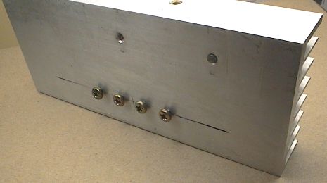
4 holes were drilled, they are spaced exactly 0.5" apart (12.7mm). They were drilled 2.78mm (7/64") to take 3mm self-tapping electrical screws as an interference fit. They were screwed in first to form a thread before doing the delicate stuff.
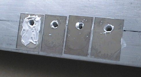
The 2 middle Mica washers were trimmed slightly thinner with a pair of sharp scissors. About 1mm (1/25") was removed from each edge.
Then heatsink goop was smeared on the Mica washers using a tiny flat screwdriver. The washers were pressed to the heatsink where they stick.
Then some more goop is added to the front side of the washers. You can see this on washer 1. All 4 washers are gooped on both sides.
Then the transistors are screwed down. IMPORTANT! There is a white plastic insulator on each screw, you can see them between the screws and the transistor tabs.
Note the correct amount of goop. It just forms a small bead around the edge of the transistors. Generally if it looks like the goop is not quite enough, then after is squishes down you find out there was enough. You can clean up the excess goop with cotton bud (Q-tip) etc. If it is this amount I wouldn't bother.
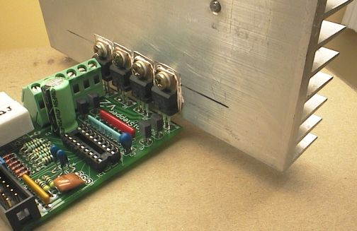
The finished setup ready to test. The heatsink will need to be supported, it should never be supported by the transistor legs alone!
Note! Generally heatsinks are mounted with the fins vertically to give convection cooling as the hot air rises. Or are fan cooled. The heatsink shown is not an ideal example of a permanent heatsink, it's just a test setup.
The heatsink should be securely screwed to the case to support its weight. The Linistepper mounts to the heat sink by the screws and leads of the TIP122, which provides for strain relief and thermal expansion. The opposite end of the Linistepper should be supported by a screw and a stand-off to the case, as shown below:
First double-check all the parts orientations. Especially the capacitors. Check the diodes, IC socket, etc.
Check resistor network RN1, it must also be oriented correctly.
Check the right color/value resistors are in the right places.
Check the soldering on the bottom (and top) of the PCB with a magnifier glass. Make sure there are no shorts. Make sure the solder joints look shiny, curved and complete.
On the PCB bottom, check the circle where the track was cut to make sure it is cut fully. Check the wire link you added to the bottom of the PCB, that it is joined to the correct places.
Using a multi-meter check across cap C3 (10uF tantalum) there should be no short between its pins (+5v and Ground).
Do the same check across C1 (470uF) to make sure there is no short between its pins (Motor + and Ground).
Check that the 4 power transistor tabs are not shorted to the heatsink.
Still with PIC NOT inserted, plug in the 10-pin header plug that connects to your control board such as the 4Axis board. This should now be supplying +5v to the Linistepper. IMPORTANT! Check that PIC socket pin 14 is +5v, and pin 5 of the socket is Ground. Double check this!
If you aren't using a break out board, here are the pins to connect starting with Pin 1 on the 2x5 header:
 Pin 1 Enable (low =
 enabled full power,
hi = low power*),
Pin 3 Direction input (hi = reverse)
Pin 5 Step input (step on positive edge)
Pin 7 Ground for Motor and driver (common),
Pin 9 +5VDC regulated
All even pins are grounded to interface common
* The enable line doe NOT actually enable or disable the controller. In either state, the controller WILL step the motor. The Linistepper uses the Enable line to select low power mode (when the enable line is HIGH) which is usefull for holding position between jobs without overheating the driver or motors.
NOTE! If you plug the 10-pin header in reversed, the Linistepper will not be harmed but the 5v regulator on your control board will be shorted and will get VERY HOT. This will be obvious because the +5v rail will suddenly drop down, close to zero volts. The 5v regulator on the control board should not be harmed either provided you check for this and kill the power within a few seconds. If the 10-pin header plug is oriented correctly, the PIC socket pins will read +5v and Ground correctly (see above test).
At this point you can disconnect power, and then insert the PIC into its socket (check orientation) but DON'T power anything up yet.
Now (still with no power) connect a motor by screwing it's wires into the 6-way screw-down terminals. NEVER CONNECT OR DISCONNECT MOTOR LEADS WITH THE POWER ON! Motor + wire(s) should go into the + terminal, and the 4 motor phase wires go into A1, A2, B1, B2. (If you don't know your motor wires check the stepper wiring page for info on identifying the stepper motor wires).
Connect motor power supply (M+ and Ground) into the screw-down terminals but don't turn the power on yet. (The M+ wire goes into the same terminal as the motor + lead).
If you are happy that everything is wired correctly and the 10-pin header is plugged in, turn on the power.
The motor should clamp ON and hold in position. The motor power supply should be supplying about 0.7 amps if header pin1 (enable) is +5v or full power maybe 1.2 to 1.6 amps? if header pin1 is at 0v. That depends on whether your driver board powers up in low power mode or full power mode.
At this point your Linistepper v2 should be working. If step pulses are applied to header pin5 (step) the motor should start turning, be aware that the motor may be turning VERY SLOW depending on the microstep mode.
Header pin3 (direction) controls the direction that the motor rotates.
Check the DIP switch settings, these set the microstep mode;
J1   J2    Mode
off  off   Full-step
ON   off   Half-step
off  ON    6th step microstep
ON   ON    18th step microstep
You can change the DIP switches while the motor rotates, it should change the motor speed and smoothness. Be aware that if the motor tries to go too fast the motor may stall.
Also:
The main Linistepper page has a troubleshooting guide, but here are a couple of the most common problems;
Fault 1: Motor clamps ON but makes no movement or sound at all.
Cause; No step signal is being received from your control board
(common).
Cause; No +5v supply (see the test above).
Fault 2: Motor clamps on but doesn't move at all, and makes a squealing
sound.
Cause; The step signal being sent from your control board is too fast,
the motor can't turn that fast so it stalls. See
Using the Linistepper for the minimum pulse widths
and frequency.
Fault 3: Motor clamps on ok, but when slow steps are sent the motor twitches
and jerks in the one spot instead of slowly rotating. (very common)
Cause; The 4 motor phase wires are connected wrong. The motor is not
harmed. You need to swap 2 motor wires AFTER TURNING THE POWER OFF. There
is information on the main page about identifying
the motor wires. If you don't know the motor wires, then swap 2 wires;
swap the A1 wire with the B1 wire. If that doesn't fix it, swap the A1 wire
with B2. When it is right the motor will start turning. NEVER CONNECT
OR DISCONNECT MOTOR LEADS WITH THE POWER ON!
Cause; The step signal is coming from a switch or other mechanical
system that is not "de-bounced" as a result, the linistepper is seeing multiple
step signals.
Cause: The step and direction signals are reversed. The motor will
only step when the direction changes, and in random directions.
Fault 4: Motor turns ok when slow steps are sent, but it turns in the
wrong direction.
Cause; Swap the A1 and A2 wires AFTER TURNING THE POWER OFF. The motor
will now turn in the correct direction. Note! Normally your CNC software
will have an option to swap motor direction but you may want to do it with
the wires so all your motors are the same. NEVER CONNECT OR DISCONNECT
MOTOR LEADS WITH THE POWER ON!
If you still don't see your motor turning nicely, set Full Step mode, supply a single step pulse at a time using a debounced switch or pulse generator, and record the voltage at each motor wire after each step. You will easily find the error in the stepping pattern, which will lead you to the phase which is not working. If none of the phases are working, check for power and ground at the PIC and for input (step, direction, mode) etc... at the PIC PIN (not the trace, the actual pin on top). If you do find one bad phase, power down and check for bad connections, solder joints, shorts, or other problems in the line between the PIC and that motor lead. If you don't find the problem, power up and check the center point between the PIC and the motor lead on that phase; that is the connection between the small transistor and the power transistor. If the signal is correct there, replace the power transistor, if it isn't correct, check the signal back towards the PIC. If the PIC is putting out the correct signal, replace the small transistor. If the PIC isn't putting out the correct signal, replace the PIC.
Phillip Harris says:
For my application, I will need to deal with having this board on a vehicle. So I'm also adding a couple tips from the Megasquirt community.One is a basic procedure, cleaning the excess solder-resin off of the board because that stuff absorbs moisture and will cause corrosion. An old toothbrush and some acetone gets most of it. When everything is done, I put a layer of silicone grease over the board to help seal it from moisture, and still be able to do any re-work.
A second thing to deal with is the crystal needs to be held to the board with some soft type of RTV silicone. I'm mounting mine bent on it's side and glued down with about 1/8th inch clearance.
(end)
| file: /Techref/io/stepper/linistep/LiniV2_bld.htm, 27KB, , updated: 2015/2/22 14:54, local time: 2025/10/30 22:03,
216.73.216.50,10-8-63-169:LOG IN
|
| ©2025 These pages are served without commercial sponsorship. (No popup ads, etc...).Bandwidth abuse increases hosting cost forcing sponsorship or shutdown. This server aggressively defends against automated copying for any reason including offline viewing, duplication, etc... Please respect this requirement and DO NOT RIP THIS SITE. Questions? <A HREF="http://www.massmind.org/techref/io/stepper/linistep/LiniV2_bld.htm"> Linistepper V2 Build Instructions</A> |
| Did you find what you needed? |
Welcome to massmind.org! |
Welcome to www.massmind.org! |
.