Manufacturing process
of the bending apparatus
|
I decided to use the nichrome wire for the heating element from the beginning. However, the structure of the exothermic part to bend the plastic board wasn't readily decided. The structure of the exothermic part is different a little from my ideal. However, because the material could not be acquired and it isn't possible not to do the manufacture simply, I did to the structure which was made this time. 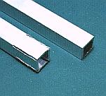 The aluminum square lumber is cut in the necessary length. I assumed that the plastic board of about 250 mm could be bent at the equipment this time and I made the width of the aluminum chassis 300 mm. I considered the interval with the stave (10mm) and the size of the part which installs the square lumber and I cut the aluminum square lumber in the 300-mm length. I cut deeply in the end of the square lumber to make the fixation part of the aluminum square lumber. 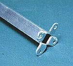 I bent the part of the notch into the 90 degrees and made the fixation part. The attention is necessary because it is possible to break the aluminum when bending it the many time. Scrape off the burr(The part which was pointed after cutting) around the fixation part with the file. Make the holes to fix. The length of the complete aluminum square lumber became 275 mm. 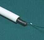 Stretche the nichrome wire according to the length of the square lumber. The attention is necessary so as not to stretch too much. Pass the stretched nichrome wire through the porcelain pipe. The length of the porcelain pipe which I used was 45 mm/piece. Because it was, I used the six pipes. This is 5 mm shorter than the square lumber. However, because the purpose of the pipe is the insulation of the nichrome wire and the aluminum square lumber, there is no problem. 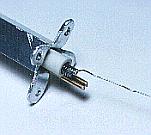 A few cracks occur because the caliber of the aluminum square lumber is 9 mm and the outside diameter of the porcelain pipe is 7 mm. I inserted the two brass sticks of 2 mm under the porcelain pipe to make the porcelain pipe and the aluminum square lumber stick.  I worried about the installation angle of the exothermic part. When bending the plastic board, it makes the part to bend touch the exothermic part and it makes soft. To make it be easy to do the work to distort a little straight first, I made the corner of the aluminum square lumber the topside. After that, it makes the bent plastic board the reverse. Then, when bending for the necessary angle, it uses the flat part of the aluminum square lumber. It works at the diagonal side a little but I think that there is no problem. Install the assembled aluminum square lumber on the aluminum board to fix the exothermic part on the stave. Let out the nichrome wire to the back of the aluminum board and put the glass fiber tube so as not to contact the other metallic part. It isn't possible to solder to the nichrome wire. Because it was, I used the crimp-style terminal to connect the nichrome wire. I connected the nichrome wire and the AC cord with the 4-mm screw to have installed in the tail of the epoxy board, using the crimp-style terminal. 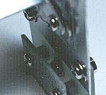 The voltage with the nearness of AC 100 V is sometimes applied to the screw which connects the nichrome wire and the AC cord. I installed the cover so as not to be shocked.The place is not the touching place generally because it is under the aluminum square lumber. I put it for the safety. 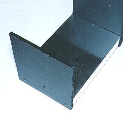 Because the depth of the aluminum chassis was 200 mm, I made the width of the stave 4 mm longer than it. This is to install the cover. I made the height of the stave 243 mm but especially, there is not a reason. The tail of the stave lets out from the chassis by 10 mm and makes the leg. The stave and the chassis are fixed by the three screws. 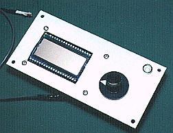 The thermometer, the temperature adjustment dial and the temperature control display LED are arranged according to the control panel drawing.  I installed each part on the cardboard and confirmed the position. With this way, the hole position of the LCD part of the thermometer can be confirmed beforehand. The position of the hole of the aluminum chassis can be correctly decided by the position of the hole which the cardboard can have opened. 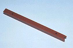 I made the central support of the exothermic part with the bakelite stick. I shaved the part which hits the exothermic part according to the angle of the aluminum square lumber. The hole to install the L metal fittings to fix on the aluminum chassis is opened at the tail of the support. The hole to install the metal fittings to install the temperature sensor is opened at the top of the support. 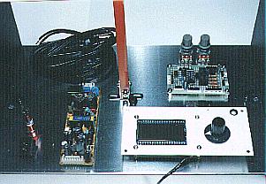 Before making the holes which install the parts, I confirmed the position to install by putting the main parts on the chassis. The interval of parts, the route of the wiring are confirmed. I examined the arrangement of the part to leave the wiring of AC 100V from the temperature control circuit as much as possible. This time, I didn't use but I think that the way of deciding the position on the hole using the paper with the size which is the same as the chassis is good.  I maked all holes according to the arrangement of the parts. I used the thread saw for the hole making of the LCD part and the power supply switch. Because the holes of the LED lamp and the neon lamp could not open only with the drill, I made big using the reamer. It makes the hole big while putting the part in the hole if approaching the size of the hole of the part and confirming the size. 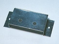 I made the stand which installs the variable resistors to control the electric power of the exothermic part with the aluminum board. Generally, because it adjusted never these resistors, I arranged inside the chassis.   When not using the bending apparatus, the AC cord is troublesome. So, I installed the AC cord binder.  The parts such as the temperature control unit, the thermometer, the power supply unit, the power supply switch are installed on the chassis. The parts such as the temperature control unit, the thermometer, the power supply unit, the power supply switch are installed on the chassis.The wiring of the AC voltage and the wiring of the DC voltage are separated as much as possible. It is easy for the temperature control circuit to be influenced by the induction of the alternating current and near the setting temperature, the relay sometimes sounds like the buzzer. The lower temperature it is, this phenomenon appears more conspicuously. The resistance value of the thermistor is big when the temperature is low. Therefore, I think that the induction of the alternating current is big. I added the 100-µF capacitors to the several places and strengthened the bypass of the low frequency. The influence of the AC voltage isn't passing away totally. I installed the cord supporter on the way of the long wire and the wire made not move.  The exothermic part is installed in the stave. I placed the exothermic part at the central support, and the height on either side made become the same and fastened the exothermic part to the stave with the screw. First, I planned to install the glass epoxy board at the four. However, the enough strength was gotten only at the two of the tops. I passed the wiring to the exothermic part through the pipe-shape plastic supporter.  I worried about how I did the structure of this part until the last. I worried about how I did the structure of this part until the last.The temperature of the exothermic part is made to rise in about 160°C. However, the temperature upper limit of the sensor is 120-150°C. Because it had exceeded the upper limit temperature when making the sensor stick to the exothermic part, I separated and installed a little distance between the exothermic part and the sensor. Because the error came out in the temperature around about separating the distance only, I covered the sensor with the aluminum board. There may are not an effect. I got the wiring of the sensor to the supporter of the central support and made it not move.  I separated the printed board of the temperature detector and the printed board of the electric power control circuit and piled the printed board of the temperature detector with the printed board of the thermometer. Because the length of the plate screw was short, I used metallic stud to keep the interval of the printed board. 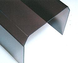 I bent the acrylic board with the 3-mm thickness and made the cover. I used "bending apparatus-2" to make this cover. Because the width of the cover is wide, it isn't possible to bend with this apparatus. 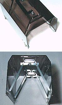 I reinforced the acrylic board using the L-shaped angle of the aluminum. In case of the practical use, even if it doesn't reinforce, there is no problem. I put the aluminum stopper to the tail of the cover not fall more than necessary.  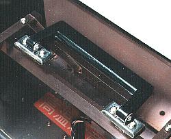 I put the handle to the top of the cover to be convenient to carry. 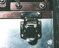 First, I made the stopper with the the phosphorus bronze board. However, because it seemed to come easily, I put the clasp tool. The bending apparatus of the plastic board was complete above.
There is an a little problem on the efficiency in the bending apparatus which was made this time. So, make the contents of this page the reference when you make the other equipment. |