Parts explanation
of bending apparatus-2
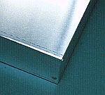 I used the aluminum case for the body (the stand part) of the bending apparatus. I used the two ones with the 200-mm width, the 50-mm height, the 100-mm depth, the 1-mm thickness.  I am using the nichrome wire for the exothermic part. I put the heating element in the aluminum square lumber and use as the bend bench. The porcelain pipe is used to insulate the nichrome wire and the aluminum square lumber. For the details of the making, refer to the first machine. In the exothermic part this time, the brass stick isn't used. 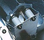  I used the aluminum board of 0.5 mm for the fixation metal fittings. In case of the aluminum board of 0.5 mm, it is possible to cut easily with the scissors for the metal. It is the a little exaggerated expression but it is possible to make like the paper workmanship. 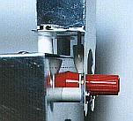 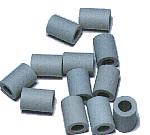 I used the porcelain pipe between the exothermic part and the stave to support the exothermic part and between the stave and the chassis as the spacer. First I fixed the stave on the chassis directly. In the case, the heat in the exothermic part spread through the chassis gradually and the chassis became hot. Therefore, I separated the stave from the chassis using the spacer. 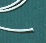 This glass fiber tube is used to insulate the lead wire of the nichrome wire. Because the temperature of the lead wire rises too, the endured glass fiber tube is used for the heat. 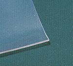 I am using this sheet for the protector for the porcelain pipe in the exothermic part to make not come and the cushion of the pipe to be using with the spacer. The porcelain pipe which was fixed with the screw has the possibility that it damages when the heat expands it. So, I put in the silicon sheet. 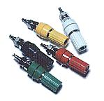 Because the nichrome wire can not do the soldering, I used the crimp-style terminal. The wiring of the AC cord lets through the inside of the chassis. So, I am wiring with the nichrome wire using the Johnson terminal. 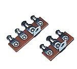 I did the wiring of the AC cord and the putting the temperature adjustment resistor using this terminal board. 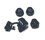 When passing the cord through the hole of the aluminum chassis, there is a gravity which the cord and the chassis connect with to rub them being possible. It is protecting with the plastic protector. 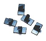 These supporters are used to fix so as not for the cord to become troublesome. 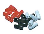 Because the connection part of the wiring was the inside of the chassis, there was not necessity but I used because of the advantage. 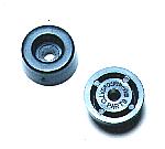 To make the crack for the ventilation under the chassis, I installed the plastic leg under the chassis. 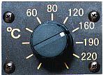 The temperature is adjusted with the variable resistor of the electric power control circuit. 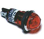 This lamp is used to display the power supply ON/OFF condition of the nichrome wire. The neon lamp is doing the structure which arranged the pole which faced the inside of the glass pipe which the neon was enclosed. The neon in the neighborhood of the pole shines with the discharge when the voltage is applied to the pole. Because the neon lamp becomes that it is easy for the electric current to flow when the discharge begins, the resistor (about 100 K-ohm) must be put in series. This time, the lamp which I used is the type that the resistor is had. This lamp isn't too light but there is no problem in the use as the indicating lamp. It is convenient because it is possible to make light up by AC 100V directly and few flowing electric currents occur. 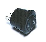 This is the switch which ON/OFF the power supply supply to the exothermic part. 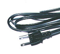 I used the cord for 700 W. 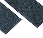 When not using the equipment, the power input cable can be fixed with this tape. This tape is the tape to use by the sewing and so on. The loop-shape fibers are put to the tape of the one. And a lot of hooks of the nylon which did the J type are put to the tape of the other. Both can be easily attached or removed.  This is the bidirectional triode thyristor(TRIAC) which I am using this time. Because the circuit this time doesn't pass the big electric current, it doesn't need the heatsink. I put the heatsink with the 6-mm thickness for the safety. The triac which was used this time can pass the 16-A electric current. This time, it passes only the 1 or 2-A electric current. The details see "Electric power controller". 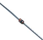 This is the trigger diode which gives the triac the trigger pulse. It is using N413. The details see "Electric power controller". 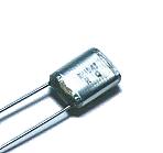 This is the capacitor which controls the phase of the pulse to add to the gate of the triac. It is using the 0.1-µF capacitor. The details see "Electric power controller". 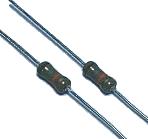 These are the resistors for the electric power control and the hysteresis prevention. The 1/2-W resistors are used. The details see "Electric power controller". 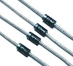 It is used for the hysteresis prevention circuit. The details see "Electric power controller".   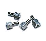 I use this to install the printed board to the case. There is not necessity of the metal. I used the one with the 5-mm height for the 3-mm screw.  |